
Operating Instructions


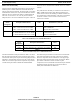
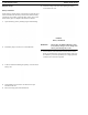
Table Of Contents
- CHAPTER 1 Introduction
- CHAPTER 2 BTR-800 Base Station
- CHAPTER 3 TR-800 Beltpack
- CHAPTER 4 TR-825 Beltpack
- CHAPTER 5 Initial Equipment Setup
- Unpacking
- Antenna Connection
- Antenna Polarization
- Distance between Antennas
- Antenna Placement
- Improving Reception and Increasing Range
- Base Station Set-up
- Location
- Power Connection
- Transmit Switches
- Internal Transmit Switches
- Intercom Switch
- Intercom Interface
- Dual Listen Functionality
- Auxiliary Input/Output
- Internal Auxiliary Input Routing Switch
- Stage Announce / Relay Contacts
- Base Station Link
- Beltpack Setup
- Antenna Connection
- Transmit Mode
- Headset Connection
- CHAPTER 6 Pre-Walk-Thru Checklist
- CHAPTER 7 System Operation
- Frequency Plan Overview
- Factory-Defined Groups
- User-Programmable Groups
- System Quick Start
- Base Station Operation
- Power
- Local Headset
- Portable Station Connect
- Intercom A and B
- Auxiliary
- Display Contrast
- BTR-800 Menu Structure
- Main Screen Flowchart
- Power-Up Screen
- Operating Screen
- Beltpack Activity Code Definitions
- Group/Channel Select
- Group/Frequency Select
- Frequency Edit (User-Programmed Groups Only)
- ClearScan™
- Special Key Sequences
- Lockout
- Copy
- 1st Use Default
- Factory Default
- Beltpack Operation
- On/Off and Volume Control
- Battery Check
- Talk Button
- Microphone Gain
- Audio Channel Select Button
- Stage Announce (SA)
- Wireless Talk Around (WTA)
- TR-800 Menu Structure
- Beltpack Menu Structure
- Power-Up Screens
- Group/Channel Screen
- Transmit Screen
- Receive 1 Screen
- Receive 2 Screen
- ClearScan™
- Stage Announce Enable/Disable
- Wireless Talk Around Enable/Disable
- Audio Channel A or B Disable/Enable
- Talk Button Latch on/Latch off
- Special Key Sequences
- Lockout
- 1st Use Default
- Factory Default
- TR-825 Menu Structure
- CHAPTER 8 System Walk-Thru
- CHAPTER 9 Troubleshooting
- CHAPTER 10 Tech Tips
- CHAPTER 11 Battery Information
- CHAPTER 12 Intercom Systems Specifications
- CHAPTER 13 Accessories and Replacement Parts
- CHAPTER 14 Certification Information
- CHAPTER 15 Three Band Base Stations

BTR-800, TR-800, TR-825 Initial Equipment Setup 31
Base Station Link
This RJ-45 type jack allows the connection of wireless talk
around (WTA) to two base station of the same frequency bands.
This allows WTA on I/C channel A and WTA on I/C channel B
to be the carried through to the other base station attached
together via this jack.
FIGURE 30.
Base Station Link Cable
WTA channel A and channel B is contained within a base
station unless the transmit power is off. If it is off, the WTA
audio is routed through the base station link cable to the other
base that has its transmitter on.
A cable to accomplish this task is NOT supplied, but can easily
be made with common category 5 (CAT-5) or later wiring.
In fact, the most common 10BaseT Ethernet patch cables, 568-B
wired cables, can be used to connect bases together. The
required cable is shown below.
The regular two-wire intercom channels are passed from base to
base via the wired intercom cables and do not require the base
station link cable.
FIGURE 28.
Base Station – Rear Panel
FIGURE 29.
Two Stand Alone Base Stations Connected Together