
Operating Instructions


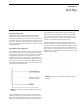

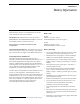


Table Of Contents
- CHAPTER 1 Introduction
- CHAPTER 2 BTR-800 Base Station
- CHAPTER 3 TR-800 Beltpack
- CHAPTER 4 TR-825 Beltpack
- CHAPTER 5 Initial Equipment Setup
- Unpacking
- Antenna Connection
- Antenna Polarization
- Distance between Antennas
- Antenna Placement
- Improving Reception and Increasing Range
- Base Station Set-up
- Location
- Power Connection
- Transmit Switches
- Internal Transmit Switches
- Intercom Switch
- Intercom Interface
- Dual Listen Functionality
- Auxiliary Input/Output
- Internal Auxiliary Input Routing Switch
- Stage Announce / Relay Contacts
- Base Station Link
- Beltpack Setup
- Antenna Connection
- Transmit Mode
- Headset Connection
- CHAPTER 6 Pre-Walk-Thru Checklist
- CHAPTER 7 System Operation
- Frequency Plan Overview
- Factory-Defined Groups
- User-Programmable Groups
- System Quick Start
- Base Station Operation
- Power
- Local Headset
- Portable Station Connect
- Intercom A and B
- Auxiliary
- Display Contrast
- BTR-800 Menu Structure
- Main Screen Flowchart
- Power-Up Screen
- Operating Screen
- Beltpack Activity Code Definitions
- Group/Channel Select
- Group/Frequency Select
- Frequency Edit (User-Programmed Groups Only)
- ClearScan™
- Special Key Sequences
- Lockout
- Copy
- 1st Use Default
- Factory Default
- Beltpack Operation
- On/Off and Volume Control
- Battery Check
- Talk Button
- Microphone Gain
- Audio Channel Select Button
- Stage Announce (SA)
- Wireless Talk Around (WTA)
- TR-800 Menu Structure
- Beltpack Menu Structure
- Power-Up Screens
- Group/Channel Screen
- Transmit Screen
- Receive 1 Screen
- Receive 2 Screen
- ClearScan™
- Stage Announce Enable/Disable
- Wireless Talk Around Enable/Disable
- Audio Channel A or B Disable/Enable
- Talk Button Latch on/Latch off
- Special Key Sequences
- Lockout
- 1st Use Default
- Factory Default
- TR-825 Menu Structure
- CHAPTER 8 System Walk-Thru
- CHAPTER 9 Troubleshooting
- CHAPTER 10 Tech Tips
- CHAPTER 11 Battery Information
- CHAPTER 12 Intercom Systems Specifications
- CHAPTER 13 Accessories and Replacement Parts
- CHAPTER 14 Certification Information
- CHAPTER 15 Three Band Base Stations

CHAPTER 10
Tech Tips
Frequency Interaction
Unfortunately, radio frequency (RF) channels cannot be
randomly selected for use in radio devices. They must be
selected to avoid know frequencies in use, FCC restrictions on
the location of devices, and even interference between your own
RF devices. The factory defined frequencies (Groups 01A-24)
selected by RTS for this wireless system are chosen to minimize
possible interference.
Microphone Gain Adjustment
The microphone gain controls on the base station and beltpack
are set to mid-levels by the factory. In most cases this setting
will work fine and only on loud speech will the over-modulation
(OM) indicator light. However, in environments where the
background noise is loud or the user has a strong/quiet voice,
the gain control will need to be adjusted. In Figure 40 the gain is
set correctly. The user’s root-mean-square (RMS) sound level is
well
b
elow the OM threshold and only on peaks does his or her
voice flash the OM indicator light.
FIGURE 40. Low Noise Environment Microphone Gain Set
Correctly
Figure 41 displays the same gain setting as in Figure 40 but
brought into a high noise environment. The user’s voice now
lights the OM indicator all the time he or she speaks due to the
higher noise plus the user speaking louder. The result on the
system is distortion on louder speech. The microphone gain
must be reduced. The same applies to a user with a powerful
voice. If someone sets the system mic gain to their voice and
user has a much stronger voice, then the gain will need to be
reduced, even if the background noise is the same.
Always remember to set the microphone gain based on the
situation and location in which the equipment will be used. If
the equipment is used on the field during a football game, set the
gain based upon a loud stadium, NOT a quiet stadium 2 hours
before a game. If a production studio users has a quiet voice, set
the gain to their voice and NOT the stage hand’s loud voice who
helped set up the system.
FIGURE 41. High Noise Environment Microphone Gain Set
Too High