
Operating Instructions


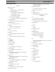

Table Of Contents
- CHAPTER 1 Introduction
- CHAPTER 2 BTR-800 Base Station
- CHAPTER 3 TR-800 Beltpack
- CHAPTER 4 TR-825 Beltpack
- CHAPTER 5 Initial Equipment Setup
- Unpacking
- Antenna Connection
- Antenna Polarization
- Distance between Antennas
- Antenna Placement
- Improving Reception and Increasing Range
- Base Station Set-up
- Location
- Power Connection
- Transmit Switches
- Internal Transmit Switches
- Intercom Switch
- Intercom Interface
- Dual Listen Functionality
- Auxiliary Input/Output
- Internal Auxiliary Input Routing Switch
- Stage Announce / Relay Contacts
- Base Station Link
- Beltpack Setup
- Antenna Connection
- Transmit Mode
- Headset Connection
- CHAPTER 6 Pre-Walk-Thru Checklist
- CHAPTER 7 System Operation
- Frequency Plan Overview
- Factory-Defined Groups
- User-Programmable Groups
- System Quick Start
- Base Station Operation
- Power
- Local Headset
- Portable Station Connect
- Intercom A and B
- Auxiliary
- Display Contrast
- BTR-800 Menu Structure
- Main Screen Flowchart
- Power-Up Screen
- Operating Screen
- Beltpack Activity Code Definitions
- Group/Channel Select
- Group/Frequency Select
- Frequency Edit (User-Programmed Groups Only)
- ClearScan™
- Special Key Sequences
- Lockout
- Copy
- 1st Use Default
- Factory Default
- Beltpack Operation
- On/Off and Volume Control
- Battery Check
- Talk Button
- Microphone Gain
- Audio Channel Select Button
- Stage Announce (SA)
- Wireless Talk Around (WTA)
- TR-800 Menu Structure
- Beltpack Menu Structure
- Power-Up Screens
- Group/Channel Screen
- Transmit Screen
- Receive 1 Screen
- Receive 2 Screen
- ClearScan™
- Stage Announce Enable/Disable
- Wireless Talk Around Enable/Disable
- Audio Channel A or B Disable/Enable
- Talk Button Latch on/Latch off
- Special Key Sequences
- Lockout
- 1st Use Default
- Factory Default
- TR-825 Menu Structure
- CHAPTER 8 System Walk-Thru
- CHAPTER 9 Troubleshooting
- CHAPTER 10 Tech Tips
- CHAPTER 11 Battery Information
- CHAPTER 12 Intercom Systems Specifications
- CHAPTER 13 Accessories and Replacement Parts
- CHAPTER 14 Certification Information
- CHAPTER 15 Three Band Base Stations

FIGURE 3.
BTR-800 - Rear Panel
10 BTR-800 Base Station BTR-800, TR-800, TR-825
1. Receive Antenna – Female TNC Connector. Color band on
antenna must match color dot on base station.
2. Transmit Power Switch – HIGH = Transmitters at full
power. NORMAL = Transmitters 10dB below full power.
3. Transmit ON/OFF Switch – Turns the transmitters on or
off.
4. I/C Select Switch – Set to the appropriate 2-wire intercom
type being interfaced to the unit. Set to either Telex, RTS, or
Clear-Com.
5. Base Station Link Jack – When two base stations are
connected through this jack, it allows wireless talk around
(WTA) from the beltpacks to be routed from the system
with it’s transmitters off to the system with it’s transmitters
on.
6. Relay Contact – A dry contact closure which is activated
when a beltpack user presses the stage announce (SA)
button. Normally Open (NO). 1 Amp at 24V maximum.
7. Intercom A – Interface to wired intercom system A.
2-Wire – Male and female 3-pin XLR connectors wired in
parall
el. The connectors are switched to the appropriate
intercom configuration via the I/C Select Switch.
WARNING: Excessive current through the loop thru ports
will damage the intercom! Do not exceed 200
mA current in the 2-wire loop thru circuits.
4-Wire – An RJ-11 type jack compatible with Matrix type
intercom systems.
8. Intercom B – Interface to wired intercom system B.
2-Wire – Male and female 3-pin XLR connectors wi
red in
parallel. The connectors are switched to the appropriate
intercom configuration via the I/C Select Switch.
WAR NING : Excessive current through the loop thru ports
will damage the intercom! Do not exceed 200
mA current in the 2-wire loop thru circuits.
4-Wire – An RJ-11 type jack compatible with Matrix type
intercom systems.
9. Auxiliary Input/Output – One 3-pin female XLR input
connector and one 3-pin male XLR output connector.
10. Stage Announce Output – Passes the audio from any of
the base stations’s beltpack that have selected stage
announce (SA).
11. Power – IEC receptacle. Accepts 100–240 VAC, 50–60 Hz.
12. Transmit Antenna – Female TNC Connector. Color band
on antenna must match color dot on base station.