
Operating Instructions

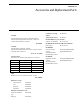
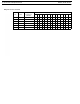


Table Of Contents
- CHAPTER 1 Introduction
- CHAPTER 2 BTR-800 Base Station
- CHAPTER 3 TR-800 Beltpack
- CHAPTER 4 TR-825 Beltpack
- CHAPTER 5 Initial Equipment Setup
- Unpacking
- Antenna Connection
- Antenna Polarization
- Distance between Antennas
- Antenna Placement
- Improving Reception and Increasing Range
- Base Station Set-up
- Location
- Power Connection
- Transmit Switches
- Internal Transmit Switches
- Intercom Switch
- Intercom Interface
- Dual Listen Functionality
- Auxiliary Input/Output
- Internal Auxiliary Input Routing Switch
- Stage Announce / Relay Contacts
- Base Station Link
- Beltpack Setup
- Antenna Connection
- Transmit Mode
- Headset Connection
- CHAPTER 6 Pre-Walk-Thru Checklist
- CHAPTER 7 System Operation
- Frequency Plan Overview
- Factory-Defined Groups
- User-Programmable Groups
- System Quick Start
- Base Station Operation
- Power
- Local Headset
- Portable Station Connect
- Intercom A and B
- Auxiliary
- Display Contrast
- BTR-800 Menu Structure
- Main Screen Flowchart
- Power-Up Screen
- Operating Screen
- Beltpack Activity Code Definitions
- Group/Channel Select
- Group/Frequency Select
- Frequency Edit (User-Programmed Groups Only)
- ClearScan™
- Special Key Sequences
- Lockout
- Copy
- 1st Use Default
- Factory Default
- Beltpack Operation
- On/Off and Volume Control
- Battery Check
- Talk Button
- Microphone Gain
- Audio Channel Select Button
- Stage Announce (SA)
- Wireless Talk Around (WTA)
- TR-800 Menu Structure
- Beltpack Menu Structure
- Power-Up Screens
- Group/Channel Screen
- Transmit Screen
- Receive 1 Screen
- Receive 2 Screen
- ClearScan™
- Stage Announce Enable/Disable
- Wireless Talk Around Enable/Disable
- Audio Channel A or B Disable/Enable
- Talk Button Latch on/Latch off
- Special Key Sequences
- Lockout
- 1st Use Default
- Factory Default
- TR-825 Menu Structure
- CHAPTER 8 System Walk-Thru
- CHAPTER 9 Troubleshooting
- CHAPTER 10 Tech Tips
- CHAPTER 11 Battery Information
- CHAPTER 12 Intercom Systems Specifications
- CHAPTER 13 Accessories and Replacement Parts
- CHAPTER 14 Certification Information
- CHAPTER 15 Three Band Base Stations

CHAPTER 13
Accessories and Replacement Parts
ALP-600
520-760 mHz Bi-Directional Log Periodic Antenna
Includes mounting hardware and 10 feet (3 meters) of
coaxial cable with TNC Connectors.
PN 878896
ALP-450
450-900 mHz Log Periodic Antenna
Includes mounting hardware and 10 feet (3 meters) coaxial
cable with TNC connectors.
Order No. 71147000
Antenna Cables
Special low loss antenna cables with TNC Connectors
Model No. Length Order No.
CXU-10 10 Ft (3 meters) 690419
CXU-25 25 Ft (7.6 meter) 71151-025
CXU-50 50 Ft (15 meter) 71151-050
CXU-75 75 Ft (23 meter) 71151-075
CXU-100 100 Ft (30 meter) 71151-100
AB-2
Bracket for 1/2-wave Antenna with 10ft. of coax
PN 71138000
BTR Power Cords
North America 550024013
U.K. 550024002
European 550024000
Australian 550024018
BTR Intercom Dummy Load
Audiocom (TELEX)
type
PN 878935
RTS type PN 878990
SA Relay screw plug
adapter
PN 2862046
TR LCD/switch cover PN 450364
BP-700 TR Battery pack, alkaline
(batteries not included) PN 71315-000
BP-800NM TR Nickel-Metal Hydride 2200mAh
Battery pack PN 71315-002
BC-800NM4
Four Slot “Smart”
Charger
with Nickel Metal
Hydride Battery Packs
US/Canada PRD00007008
EURO PRD00007009
BC-800NM
Single Slot “Smart”
Charger
with Nickel Metal
Hydride Battery Packs
US/Canada PRD00007006
EURO PRD00007007