Operating Instructions RKP-4B, RKP-4 Professional Wireless Keypanel System
Table of Contents Section 1 Introduction . . . . . . . . . . . . . . . . . . . . . . . . . . . . . . . . . . . . . . . . . . . . . . . . . . . . . . . . . . . . . . . . .1-1 General Description . . . . . . . . . . . . . . . . . . . . . . . . . . . . . . . . . . . . . . . . . . . . . . . . . . . . . . . . . . . . . . . . . . . . . . .1-1 System Features . . . . . . . . . . . . . . . . . . . . . . . . . . . . . . . . . . . . . . . . . . . . . . . . . . . . . . . . . . . . . . . . . . . . . . . . . .
Table of Contents (continued) Section 7 RKP-4 Operation . . . . . . . . . . . . . . . . . . . . . . . . . . . . . . . . . . . . . . . . . . . . . . . . . . . . . . . . . . . . . .7-1 Basic Operational Description . . . . . . . . . . . . . . . . . . . . . . . . . . . . . . . . . . . . . . . . . . . . . . . . . . . . . . . . . . . . . . .7-1 System Quick Start . . . . . . . . . . . . . . . . . . . . . . . . . . . . . . . . . . . . . . . . . . . . . . . . . . . . . . . . . . . . . . . . . . . .
Section 1 Introduction General Description The RTS RKP-4 UHF wireless keypanel system is the ultimate in reliable, high performance, encrypted full duplex communications. The RKP-4 system includes the RKP-4B frequency agile base station and a RKP-4 frequency agile beltpack. The RKP-4 system is ideal for users who want the freedom of a wireless keypanel and want full access to the most commonly used keypanel features.
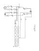
1-2 Figure 1-1 RKP-4B -Block Diagram
1-3 Figure 1-2 RKP-4 Block Diagram
1-4 Blank
Section 2 Controls and Connections - Front Panel RKP-4B Base Station Figure 2-1 RKP-4B -Front Panel 1. On/Off Switch: Turns the base station on/off 2. [Menu] and [Set] buttons: Used to select menus and set options on the LCD. 3. Backlit LCD w/Contrast Adjust: Adjust the level of contrast to the LCD. 4. [Up] and [Down] buttons: Used to select menus and set options on the LCD. 5. Peak Aux Level Light: Will flash red when the auxiliary input level into the base station is high. 6.
Controls and Connections - Rear Panel Figure 2-3 RKP-4B - Rear Panel 12. Relay Contacts: Normally Open. When activated it will close. 13. Receive Antenna Connector: TNC Female connector. The color dot near the connector must match the color of the antenna. 14. Auxiliary Connector: RJ-12 connector used to connect balanced auxiliary audio into and out of a base station. 15. CAN Bus: RJ-45 connectors used to connect a base station to a CAN type of communications bus. 16.
Section 3 RKP-4 Beltpack Figure 3-1 RKP-4 Top Panel Controls and Connections - Top Panel 1. On/Off & Volume Control: Turns the beltpack power on and controls headset volume. 2. Intercom Buttons: Assignable for several types of operation, including talk only, listen only, talk with autolisten, and all-call (where activating the key also activates all keys to the left of that key). Keys feature momentary or latching operation.
Figure 3-2 RKP-4 Rear Panel/Connector/Antennas 7. [MENU] and [SET] buttons: Used to select menus and set options on the LCD. 8. LCD (Liquid Crystal Display) 9. [UP] and [DOWN] buttons: Used to select beltpack options on the LCD. 10. Headset Connector: Female XLR connector. A dynamic or electret headset microphone is automatically detected. 11. Battery Latch: Press down to enable the battery pack to be released.
Section 4 Specifications RKP-4B Specifications Overall RF Frequency Range . . . . . . . . . . . . . . . . . . . . .482 - 608 MHz, 614 - 746 MHz in 18 MHz TX and RX bands Power Requirements . . . . . . . . . . . . . . . . . . . . . . . . . . . . . . . . . . . . . . . . . . . . . . . .12-15 Volts AC/DC @ 1 Amp o o o o Temperature Range . . . . . . . . . . . . . . . . . . . . . . . . . . . . . . . . . . . . . . . . . . . . . .-4 F to 130 F (-20 C to 55 C) Dimensions . . . . . . . . . . . . . . . . . . .
RKP-4 Specifications Overall RF Frequency Range . . . . . . . . . . . . . . . . . . . . . .482 - 608 MHz, 614-746 MHz in 18 MHz TX and RX bands Power Requirements . . . . . . . . . . . . . . . . . . . . . . . . . . . . . . . . . . . . . . . .6 “AA” Cells Alkaline (NiMH optional) Current Draw . . . . . . . . . . . . . . . . . . . . . . . . . . . . . . . . . . . . . . . . . . . . . . . . . . . . . . . . . . . . . . .190 mA (Typical) o o o o Temperature Range . . . . . . . . . . . . . . . . . . . . . . . .
Section 5 Initial Equipment Set-Up Unpacking Unpack your RKP-4 system. Below are the items that should come with our base station and each belt pack. Contact the shipper or your dealer immediately if anything is damaged or missing.
Rack Mounting Rack Mounting Two Base Stations The rack mounting brackets come with each RKP-4. These Side-by-Side brackets may be used to mount a single base station in a 19” wide rack or mount two base stations side by side in a rack. Figure 5-1 shows the three brackets that come with a base station. 1. Remove the four pan head screws (two on each side) closest to the front panel. 2. Place the double unit side brackets on the sides of the base stations you wish closest to the edge of the rack. 3.
Antenna Connection The base station is supplied with two (2) antennas. One 1/2-wave antenna for Transmit and one 1/2-wave for Receive. The antennas have TNC male connectors. The frequency range of the antennas should match the receiver and transmitter of the base station. Match the color code on the antenna with the color code on the base station. Attach the transmit 1/2-wave antenna to the antenna input receptacle labeled “TRAN” on the right side of the rear panel. The antenna should be vertically aligned.
Keep the distance between the base station and the beltpacks as short as possible. The greater the distance, the weaker the signal. Make sure the “signal paths” between the base station and beltpacks are unobstructed. You should be able to visibly locate the base station antennas at all times for best performance. Attempting to operate the wireless intercom system through or around walls, ceilings, metal objects, etc. will reduce system range and performance.
Figure 5-11 Antenna Placement 5-5
5-6 Blank
Section 6 RKP-4B Operation Basic Operational Description System Quick Start The RKP-4B is the base station for the RKP-4 beltpack. The wireless keypanel system is a full duplex (simultaneous talk and listen) audio system that is designed to work with Adam, Adam CS and Zeus and CRONUS Digital Matrix Intercom Systems. The RKP-4’s operation is very similar to the MKP-4, BKP-4, TKP-4, and WKP-4, four button wired keypanels. The following is a list to quickly get a base station and beltpack operating.
Figure 6-1 RKP-4B Rear Connectors Interfacing to the RKP-4B TX/RX Antennas Auxiliary Port The TNC jack marked “RCV” is for the receive antenna. The TNC jack marked “TRAN” is for the transmit antenna. The base station will come with two 1/2 wave antennas. Always match the color dot on the base station with the colored band on the antenna. This jack allows a balanced input auxiliary signal to be placed into the base station. It also allows a balanced output signal to be brought out of the base station.
CAN Bus Relay The CAN bus allows the connection of multiple base stations to a Frequency Manager. The Frequency Manager then can be used to set all the base stations to a frequency plan plus set a variety of other options on the base station. The base stations then can program frequencies of their beltpacks via an overthe-air link. Thus a whole system can be set-up with only a few button presses at the frequency manager. Each frequency manager can control up to 10 base stations.
Figure 6-7 Front Controls and Connector Local Headset Overmodulation: Light flashes on loudest speech = Gain OK Light flashes on all speech = Gain too High Light never flashes on loud speech = Gain too low The local base station headset allows direct communications to the beltpack. It does not connect to the Matrix. Volume Control Turn control clockwise to increase the headphone volume. Talk Button Press to enable audio path from the headset microphone.
Start-up When the RKP-4B is powered-up the 1st screen displayed is the start-up splash screen. It will be displayed for about 2 seconds. This screen contains the software version and channel map versions that are loaded into the base station. The following screen has software version sb10022, and channel map versions B0001 and 30001. This indicates it is a B3 unit. After 2 seconds the status screen will appear. See the “RKP4B Menu Structure” section for a flowchart of the main screens.
System Settings Base Main Settings The systems settings allows a number of base station characteristics to be set. This includes base name, base number, aux type, base TX power, Matrix configuration options, sidetone and frequencies. Name and Number The name of the base station may be set to any 10 digit alphanumeric character. For example, the name of the user may be entered. This provides an easy identifier to the user as to who’s base station it is.
Changing the Auxiliary types, TX power and Sidetone 1. From the status screen hit
Matrix Settings Setting the 4-Wire, Aux and Relay Options There are four options to set in this screen. Any changes in these settings requires the power of the beltpack and the base station to be reset. 1. From the status screen hit
ClearScanTM Press and hold
Alternate Screen Press and hold
Section 7 RKP-4 Operation RKP-4 Operation Basic Operational Description The RKP-4 is the beltpack for the RKP-4 keypanel system. The wireless system is a full duplex (simultaneous talk and listen) audio system that is designed to work with Adam, Adam CS and Zeus and CRONUS Digital Matrix Intercom System. The RKP-4’s operation is very similar to the MKP-4, TKP-4, and WKP-4, four button wired keypanels. 4. Press
Battery Installation Ensure that the On/Off volume control knob is turn off. Press down and hold down the battery release latch, slide the battery pack about 1/8 inch back, toward the latch, until it stops. Then lift battery pack out. Replace batteries as follows: 1. 2. Pull battery strap to remove low or dead batteries. 3. Load new batteries following the polarity as shown in battery case. Open the battery pack by inserting finger nail and lifting. 5. Be sure strap goes under batteries. 6.
Figure 7-3 RKP-4 Controls Headset Connection Antenna Connection The headset connector is a XLR type connector. Four or five pin headset connectors may be installed in the unit. See the “RKP-4 Controls and Connections” section for information on the pinouts. A dynamic or electret headset microphone is automatically detected by the beltpack and a bias voltage supplied if needed. The beltpack comes with two detachable, screw type, 1/4 wave antennas.
Figure 7-4 RKP-4 Controls RKP-4 Top Panel On/Off & Volume Control: Turns the beltpack power on and controls headset volume. Call Waiting Display: 4-character, alphanumeric display for incoming caller names. Intercom Buttons: Assignable for several types of operation, including talk only, listen only, talk with auto-listen, and allcall (where activating the key also activates all keys to the left of that key). Keys feature momentary or latching operation.
Group and Channels The first screen the beltpack displays on the rear LCD,after power-up, is the group / channels screen. This screen shows the currently selected group followed by the receive and transmit channels where the unit is set. Editing Group / Channels 1. Push to edit the group. The group number will begin flashing. 2. Select the desired group with the, / arrow buttons. 3. Push to accept the group. The receive channel letter will now begin flashing. 4.
Receive Frequency This screen displays the frequency in MHz of the beltpack receiver. The frequency is not changeable in factory defined groups. The frequency is changeable in user groups. Editing the RX Frequency (User Groups Only) 1. Set the unit to the desire user defined group and channels. See groups and Channels Instructions. The menu structure at the right (Figure 7-6) indicates how to get to the receiver frequency screen. 2. Push to edit the RX frequency. The frequency will begin flashing. 3.
Microphone Gain Encryption Code This screen displays the setting of the microphone gain of the beltpack. There are 16 possible settings. The number 0 indicates no microphone gain, the number 15 is maximum gain. Each step is about 3 dB of audio. Adjusting the Microphone Gain 1. Push at the microphone gain screen. The number will begin flashing. The encryption code screen allows the setting of four hexadecimal digits. Any combination of letters and/or numbers may be selected.
Serial Number Code Software / Channel Map Version The base serial number is required to be input to the beltpack to allow communication with that base station. The number like the encryption code, is composed of four hexidecimal digits. This extra security along with the encryption code means there is over 4 billion possible code combinations. The software and channel maps of the beltpack may be displayed from any of the main beltpack screens. Viewing the Software and Channel Map Version 1.
Entering ClearScanTM 1. 6. Press and hold
7-10 Blank
Section 8 Operation with a Matrix Startup and Operational Check Assigning Intercom Keys When power is applied, all LEDs will first flash green, then red (unless the beltpack is in dark operation. See “RKP-4 Operation”. This confirms that all LEDs are working correctly. Also, the call waiting window will display asterisks (****) then dashes (----). You can assign RKP-4 intercom keys using AZedit.
NOTE: . . You can scroll one name at a time by clicking and immediately releasing the or button. If you press and hold the button it will start scrolling slowly through the names. After a few seconds the scroll speed will increase. This is useful when you need to scroll through a long list. The following types of names may not appear in the scroll list: UPL Resources, IFB’s Relays (GPI outputs), and ISO’s.
Intercom Key Operation for Different Types of Key Assignments Basic Talk and/or Listen Key Operation: The lower button activates talk (if assigned). The upper button activates listen (if assigned). Talk and listen may be latched on or off independently by tapping up or down. NOTE: The following paragraphs describe special types of key assignments called special functions. These types of key assignments can only be set up using the AZedit software, and they are described in detail in the software help file.
Call Waiting Operation for Incoming Calls Displaying Key Assignments As previously described, the talk indicator for a key will flash when there is an incoming call to that key, and you may activate that key to talk back. Also if display call is set to enable at the base, the caller’s name will appear in the call waiting window, and you may press down on the call waiting key instead to talk back.
Section 9 RKP-4 Menu Structure Figure 9-1 RKP-4 Menu Structure 9-1
Section 10 RKP-4B Menu Structure Figure 10-1 RKP-4B Menu Structure 10-1
Section 11 Frequency Bands Frequency Bands The RKP-4B system operates in TV channels 16 to 36 and 38 to 59. This is the frequency range of 482 to 608 MHz and 614 MHz to 746 MHz. The band, TV channels and frequencies are shown in Table 2. Most bands are 18 MHz wide, however band 7 is 24 MHz wide. Bands F to E are always base transmit bands (beltpack receive bands). Bands 1 to 7 are always base receive bands (beltpack transmit bands).
Factory Group Plan There are 50 factory defined groups in a base station and beltpack. These group are organized in different ways to provide flexibility to the user on selecting frequencies. A group is composed of intermodulation free frequencies, but a group is also organized to be composed of frequencies in different combinations of the TV channels. The user then can select a group that is clear of broadcast TV channels in the area by selecting a group(s) that doesn’t use those channels.
Section 12 Troubleshooting Reread the sections of this manual to make sure you have completed system set-up properly. If you are unable to solve the problem, contact the dealer from whom you purchased the system for assistance. PROBLEM SOLUTION DISTORTION - System’s audio quality seems distorted at medium to high input levels. Reduce microphone gain by adjusting microphone gain control. HISS - System seems to produce a “hiss” which is undesirable.
12-2 Blank
Section 13 Battery Information Improper battery selection, use, installation and care are the cause of numerous wireless system failures. Alkaline Batteries: Alkaline batteries such as Mallory’s DURACELL® or Eveready’s ENERGIZER® provide the most reliable operation in wireless transceivers. The use of low cost carbon-zinc batteries is NOT recommended. Nickel-Metal Hydride Batteries: These batteries can save you money in the long run, as they can be recharged.
13-2 Blank
Section 14 RKP-4B to Matrix Cable Figure 14-1 RJ12 Intercom Cable Wiring Diagram Figure 14-2 RJ12 to 9-pin Intercom Cable Wiring Diagram 14-1
14-2 Blank
Section 15 FCC Information FCC LICENSING The Telex RKP-4B and the RKP-4 Transmitter/Receiver are Type Accepted under United States Federal Communications Commission Part 74. Licensing of Telex equipment is the User’s responsibility and licensibility depends on the user’s classification, users application, and frequency selected. Telex strongly urges the user to contact the appropriate telecommunications authority for any desired clarification. This device complies with part 15 of the FCC Rules.
15-2 Blank
Section 16 Software License End-User License Agreement for Telex® Software IMPORTANT - Please red this document carefully before using this product. THIS DOCUMENT STATES THE TERMS AND CONDITIONS UPON WHICH TELEX COMMUNICATIONS, INC. (the “COMPANY”) OFFERS TO LICENSE THE INSTALLED SOFTWARE OR PROGRAM (the “SOFTWARE”) FOR USE WITH THE PRODUCT IN WHICH IT WAS INSTALLED. YOU ARE AGREEING TO BECOME BOUND BY THE TERMS OF THIS AGREEMENT.
16-2 Blank
Section 17 Accessories and Replacement Parts ALP-600 480-800 MHz Bi-Directional Log Periodic Antenna Includes mounting hardware and 10 feet (3 meters) of coaxial cable with TNC Connectors P N. 878896 ALP-450 450-900 MHz Log Periodic Antenna Includes mounting hardware and 10 feet (3 meters) coaxial cable with TNC connectors Order No. 71147000 AB-2 Bracket for 1/2 wave Antenna with 10 ft. of coaxPN 71138000 RPK-4B Power Supply 12 VDC, 1 AMP . . . . . . . . . . . . . . . . . . . . . . . . .
17-2 Blank
TELEX COMMUNICATIONS, INC. PN 804130 Rev. A 12000 Portland Ave. South, Burnsville, MN 55337 Oct. 2005 Made in U.S.A.