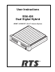
User Instructions SSA-424 Dual Digital Hybrid ADAM™, ADAM CS™, Zeus™ Intercom Systems LE V SE EL T -15 PO WE R -12 SY -9 -10 dB 0dB +1 2d +4 B dB +8 4W dB RE LE F S VE EL L ST EM -6 A -3 0 2 +3 +6 1 BA L TW 1 +9 T O +1 4W 2 CH AN SE L 2 TO 2W LE V SE EL T BA L -15 -12 SY -9 -10 dB 0dB +1 2d +4 B dB +8 4W dB RE LEV F S EL EL ST EM -6 B -3 0 1 2 BA L +3 +6 TW 1 +9 TO 4 2 W +1 CH AN SE L TO 2W 2 TM BA L SS A- 42 9350-7638-000 Rev C 10/04 4
PROPRIETARY NOTICE The RTS production information and design disclosed herein were originated by and are the property of Telex Communications, Inc. Telex reserves all patent, proprietary design, manufacturing, reproduction, use and sales rights thereto, and to any article disclosed therein, except to the extent rights are expressly granted to others. COPYRIGHT NOTICE Copyright 2004 by Telex Communications, Inc. All rights reserved.
Contents 1 Description and Specifications ........................................................................................................5 1.1 GENERAL DESCRIPTION ..................................................................................................................5 1.2 GENERAL FEATURES .......................................................................................................................5 1.3 FRONT AND BACK PANEL DESCRIPTIONS ............................................
SSA-424 USER MANUAL
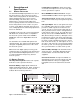
Peak Reading Level Meters: Quick and accurate visual audio level adjustment. No extra setup equipment or guesswork is required. 1 Description and Specifications 1.1 GENERAL DESCRIPTION The SSA-424 Dual Digital Hybrid intervaces two, 2wire intercom lines to two, 4-wire intercom lines. Unlike earlier analog hybrids, the SSA-424 features advanced digital signal processing to achieve automatic nulling of the 2-wire lines.
1.3 FRONT AND BACK PANEL DESCRIPTIONS 1.4 1.3.1 FRONT PANEL 2-Wire Ports Input/Output Impedance: 5,000 ohms, nominal Operating Level: -10dBu to 0 dBu, nominal Level Adjustment Range: ±12dB There is a power ON/OFF and call indicator at the left of the front panel. This indicator lights continuously when the SSA-424 is turned on and flashes when an incoming call signal is detected.
2 Installation 2.1 UNPACKING AND INSPECTING Immediately upon receipt of the equipment, carefully inspect the shipping container and the contents for any discrepancies or damage. Should there be any, notify the freight company and the dealer at once. The following items are included: Qty 1 1 1 1 Description SSA-424 Dual Digital Hybrid Power Pack with cord,100-250 VAC, 50/60Hz Warranty Card User Instruction Manual 2.
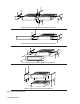
Side-By-Side Rack Mount Configuration Using an MCP1 Rack Mount Kit Single-unit Rack Mount Configuration Using an MCP2 Rack Mount Kit Console Mount Configuration Using an MCP3 Console Mount Kit Tandem Configuration Using an MCP4 Tandem Mount Kit Figure 2.
2.4.2 2.4.1 RTS TW AUDIO CONNECTIONS 1 Use standard TW intercom cables. Note, standard TW system cables can carry either one or two channels, while each hybrid in the SSA-424 can only interface one TW channel to one 4-wire channel (which channel is determined by the front panel 2W CHAN SEL switch). If your TW system cable is only carrying one channel, or if you only need to connect one of two channels, connect directly to J1A (System A) or J1B (System B).
2.4.3 CLEAR-COM AUDIO CONNECTION 1 Use standard Clear-Com 3-pin cables. Connect one Clear-Com party line to the J1A connector on the back of the SSA-424 (System A). Connect a separate Clear-Com party line to the J1B connector (System B). ✏ The SSA-424 features internal CD isolation. You can therefore connect the SSA-424 to powered Clear-Com cables, and it will not draw any power from the Clear-Com system. 2 On the SSA-424 front panel, set the System A and System B 2W CHAN SEL switches to position 2.
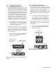
2.5 Table 1. GPI Connector Pin-out (ADAM, ADAM CS, and Zeus) 4-WIRE CALL SIGNAL CONNECTIONS ✏ These connections require the call signal option. 2.5.1 CALL SIGNAL CONNECTIONS FOR ADAM, ADAM CS, AND ZEUS You can use the General Purpose Interface (GPI) connector to interface call signals. The pin-out of the connector is the same for all of these intercom systems (Table 1).
Table 2.
2.5.2 CALL SIGNAL CONNECTIONS FOR OTHER 4WIRE COMMUNICATON SYSTEMS 2.5.2.1 4-WIRE CALL SEND AND CALL ENABLE/INHIBIT The SSA-424 accepts a switch-contact input from the 4-wire system and then generates a call signal output to the 2-wire system. The SSA-424 also accepts an optional switch contact input to enable or inhibit call signaling between the 4-wire and 2-wire systems. Figure 6 shows the typical connections.
2.6 2-WIRE CALL SIGNAL 2.6.1 CALL SIGNAL CONNECTIONS FOR AUDIOCOM, RTS TW AND CLEAR-COM The call signals are superimposed on the audio signal, so no separate call signal connections are required. However, make sure that a call enable switch or jumper is installed for Clear-Com applications as shown in Figures 5 and 6. 2.6.
3 Operation 3.1 GENERAL INSTRUCTIONS 1 Attach the power pack to the SSA-424, and apply power to all components. Confirm that the power indicator is lit on the SSA-424 front panel. 2 The power indicator flashes when a call signal is received fron a 2-wire line. The SSA-424 level displays should help to confirm which line is calling. 3 Use the level adjust trimmers (Figure 8) to fine adjust the listen levels.
4 Appendix 4.1 INTERNAL ACCESS Table 4. Mode DIP Switch Settings Sw i t c h Set t i n g s Des c r i p t i o n 1 2 3 4 1 Remove six screws from the back cover. 2 Remove the top cover. This provides access to all internal adjustments. Off Off Off Off Configuration 1, Half/Full Duplex Mode (default): Automatically switches between modes. Useful in situations where there is high ambient noise. Also useful when there is acoustic feedback.
6 Set the 2W CHAN SEL switches to either OFF position. 7 Input a 1kHz, -10dBu test signal at the 4-wire audio input. Use either connector: 9-Pin Connector Pin 7: Balanced Audio - input Pin 8: Balanced Audio + input RJ11 Connector Pin 2: Balanced Audio + input Pin 3: Balanced Audio - input 8 Adjust RV102 (System A) or RV202 (System B) while watching the bottom display (TO2W). All of the green displays should be lit and no amber displays should be lit. 9 Remove the test signal. This completes the adjustment.