USER MANUAL Model UIO-256 Universal Input/ Output Frame 9330-7499-000 Rev F, 02/2005
Proprietary Notice The RTS product information and design disclosed herein were originated by and are the property of Telex Communications, Inc. Telex reserves all patent, proprietary design, manufacturing, reproduction, use and sales rights thereto, and to any article disclosed therein, except to the extent rights are expressly granted to others. Copyright Notice Copyright© 2004 by Telex Communications, Inc. All rights reserved.
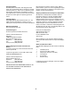
Contents 1. Introduction ......................................................................................................................................... 4 2. Description .......................................................................................................................................... 4 3. Theory of Operation ............................................................................................................................ 4 4. Installation .........................
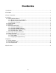
Figure 1. UIO-256 Front and Rear Panel Features 1. Introduction This manual describes the installation, programming, and operating procedures for the RTS Model UIO-256 Universal Input/Output Frame. Since the UIO-256 inputs and outputs are generally assigned using AZedit. For more information on AZedit, refer to the AZedit User Manual (9350-7532-000). 2. 4. Installation 4.1 Setting the DIP switches Description Each UIO-256 provides 16 GPI inputs and 16 GPI outputs.
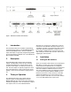
4.2 4.1.1 System Firmware 9.2.1 or Newer The UIO-256 must be configured to work in Multi-Drop mode. Set DIP switch 1-2 to the CLOSED position. Up to 16 UIO-256 frames are allowed to be connected together. Voltage Section Set the 110/220 VAC selector according to local power standards. 4.3 Mounting UIO-256 Frames are generally mounted in the front of an equipment rack near a Master Controller Breakout Panel for ADAM intercom systems or near the matrix frame for ADAM CS intercom systems.
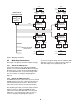
SW1 SW1 Open Open Closed 1 2 3 4 5 6 7 8 GPI OUT 1-16 Punch Block CONNECTION TO INTERCOM SYSTEM XCP-ADAM-MC, XCP-ADAM-MCJ3 or ADAM CS, J902 or ZEUS, J26 GPI IN 1-16 Punch Block 50-Pin 50-Pin J7 UIO-256 #2 In / Out 17-32 J2 J3 J4 J3 J4 J4 J3 J4 J3 UIO-256 #3 IN / OUT 33-48 J2 J7 J5 50-Pin 50-Pin GPI OUT 49-64 J7 J5 Punch Block GPI IN 49-64 Punch Block PAP/LCP-102 Panels (15 units max) J5 UIO-256 #4 IN / OUT 49-64 J2 GPI IN 17-32 Punch Block 50-Pin J7 UIO-256 #1 In / Out 1
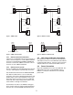
DE-9S (Female) DE-9P (Male) DE-9P (Male) DE-9P (Male) 6 1 6 1 1 2 1 2 2 TO ADAM CS, J902 2 TO XPC-ADAM-MC, J3 TO: UIO-256, J2 DE-9P (Male) DE-9P (Male) 7 7 2 2 1 1 TO: PAP-940, PAP-951, OR PAP-952 TO: PAP-940, PAP-951, OR PAP-952 DE-9P (Male) DE-9P (Male) 6 6 1 1 2 2 TO: PAP-950-50 TO: PAP-950-50 Figure 4. ADAM CS Y-Cable Figure 3.
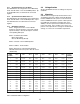
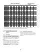
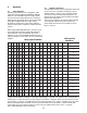
Relay Contact Pin Numbers** Relay Output Numbers* 1 2 3 4 5 6 7 8 9 10 10 11 11 12 12 13 13 14 14 15 15 16 16 NC NC Co n t ac t Co m m o n NO NO Co n t ac t 1 17 33 49 65 81 97 113 129 145 161 177 193 209 22 5 241 38 13 40 2 18 34 50 66 82 98 114 130 14 6 162 178 194 210 226 24 2 39 14 15 3 19 35 51 67 83 99 115 131 147 163 179 195 211 227 243 41 16 43 4 20 36 52 68 84 100 116 132 148 16 4 180 196 212 22 8 244 42 1
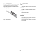
5. Operation 5.2 UIO-256 Frame Reset The UIO-256 firmware has been designed to detect and recover from errors caused by such things as lost or bad data packets. However, in the extremely unlikely event the unit stops functioning during operation, try pressing the reset switch on the front panel of the UIO256.5.3 Fuse Replacement The fuse is accessible on the rear panel power module of the UIO-256. Remove the power cord from the power module and free the fuse cartridge as shown Figure 7. Be sure 5.
5.3 Fuse Replacement The fuse is accessible on the rear panel power module of the UIO-256. Remove the power cord from the power module and free the fuse cartridge as shown Figure 7. Be sure to replace the fuse with a fuse of the same rating and type. 6.
Telex Communications, Inc.