
User manual

4
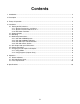
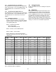
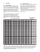
Figure 1. UIO-256 Front and Rear Panel Features
1. Introduction
This manual describes the installation, programming,
and operating procedures for the RTS Model UIO-256
Universal Input/Output Frame. Since the UIO-256
inputs and outputs are generally assigned using AZedit.
For more information on AZedit, refer to the AZedit User
Manual (9350-7532-000).
2. Description
Each UIO-256 provides 16 GPI inputs and 16 GPI
outputs. The GPI inputs can be set up as remotely
controlled keypanel keys to activate intercom ports,
party lines, GPI outputs, etc. within the intercom sys-
tem. The GPI outputs are typically assigned for activa-
tion from keypanel keys. They can be used to control
lighting or to key remote transmitters, paging systems,
etc.
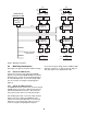
3. Theory of Operation
The UIO-256 exchanges control signals with the
intercom system via an RS-485 data connection.
Multiple UIO-256’s may also be interconnected using a
multi-drop configuration.
Note, the multi-drop configura-
tion requires version 2 of the UIO-256 firmware
.
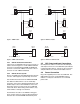
GPI inputs are connected via a 50-pin telco connector
on the back of the UIO-256. Each input requires =5 to
+18 VDC for activation. The positive input and common
connections may be provided from a remote source.
Or, +18 VDC is supplied at the connector by the UIO-
256, and may be used for input activation, with the user
supplying the external switch.
4. Installation
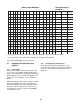
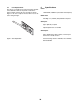
4.1 Setting the DIP switches
There are two banks of DIP switches on the back panel.
Only SW1 is currently used. There are slight differ-
ences between how UIO-256 units are configured
based on the version of firmware they are programmed
with and the ADAM or ADAM CS Firmware version.
The current shipping version of the firmware is Version
2. If the intercom system (ADAM or ADAM CS ) has
Firmware version 9.2.1 or later, Version 2 of the UIO-
256 firmware MUST be used. If the firmware in the
intercom system is older than 9.2.1, then either Version
1 or 2 of the UIO-256 firmware may be used.