
User manual

6
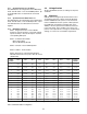
SW1
1 2 3 4 5 6 7 8
Open
Closed
SW1
1 2 3 4 5 6 7 8
Open
Closed
SW1
1 2 3 4 5 6 7 8
Open
Closed
SW1
1 2 3 4 5 6 7 8
Open
Closed
9-Pin
50-Pin
UIO-256 #1
In / Out 1-16
J4
J3
J5
J2
J7
GPI OUT
1-16
GPI IN
1-16
Punch
Block
Punch
Block
50-Pin
UIO-256 #4
IN / OUT 49-64
J2
J7
J5
J3J4
GPI OUT
49-64
GPI IN
49-64
Punch
Block
Punch
Block
50-Pin50-Pin
UIO-256 #2
In / Out 17-32
J2
J5
J7
J3 J4
GPI OUT
17-32
GPI IN
17-32
Punch
Block
Punch
Block
50-Pin50-Pin
UIO-256 #3
IN / OUT 33-48
J2
J7
J5
J3
J4
GPI OUT
33-48
GPI IN
33-48
Punch
Block
Punch
Block
UIO-256 #3
IN / OUT 33-48
PAP/LCP-102 Panels
(15 units max)
J2
J7
J5
J3
J4
50-Pin50-Pin
CONNECTION TO
INTERCOM SYSTEM
XCP-ADAM-MC
XCP-ADAM-MC, J3
ADAM CS, J902
ZEUS, J26
or
or
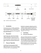
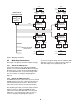
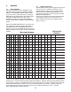
Figure 2. Multi-Drop Connections
4.4 Multi-Drop Connections
See Figure 2 for typical connections and DIP settings.
4.4.1 UIO-256 to ADAM System
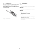
Connect the end of the 9-pin cable marked ADAM
System to J3 of the XCP-ADAM-MC Master Controller
Breakout Panel. Connect the end marked UIO-256 to
J2 of the UIO-256 Frame. If you need a longer cable,
you can construct one using the wiring diagram in
Figure 5.
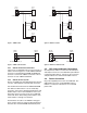
4.4.2 UIO-256 to ADAM CS System
For ADAM CS intercom systems, the connector marked
“ADAM System” on the 9-pin cable must be replaced
with the provided female connector. Disconnect the
wires and reconnect them to the same pin numbers.
After modifying the cable, connect the newly attached
female connector to J902 of the ADAM CS frame.
Connect the end marked “UIO-256” to J2 of the UIO-
256 frame. If you need a longer cable, you can con-
struct one using the wiring diagram in Figure 6.
To connect a Program Assign Panel or additional UIO-
256 units, construct a “Y” cable as shown in Figure 4.
This cable replaces the supplied 9-pin cable.