
Specifications


Model 9762 – Dual Combo Owners Manual
7 Operation
The 9762 is designed for convenience and ease of use. In general you
should experiment with a variety of microphones, placements and
settings to achieve best results. The 9762 works well with all types of
balanced microphones (dynamic and condenser) and is exceptionally
suited for use with ribbon type microphones.
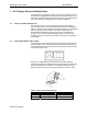
The preamplifier may be located in the studio control room or in the
recording room itself. Ideally there should be a minimum of additional
cables, boxes or connectors between the unit and the microphones for
best results. The use of high-quality microphones and cables with gold
connectors are highly recommended. Always insure the unit is properly
grounded to prevent undesirable operation.
7.1 Gain and Level Adjustments
In normal use the output LEVEL control should be set to the maximum
position (fully CW). The LEVEL control acts as a master fader control for
overall output level adjustment. The line amplifier input stage is sourced
from the LEVEL control and provides up to 10 dB gain. Thus, the output
LEVEL control is used for any adjustment or trimming of the master
output level.
Typically the line output of the preamplifier directly feeds a track on a
recorder or other piece of inline gear. Always start with the lowest setting
on the GAIN switch (fully CCW in the –20 dB position) and increase the
sensitivity to obtain the desired record level. If the output level is slightly
higher than desired, trim the output level back using the LEVEL control.
The SP signal present indicator lights to indicate signal activity. Under
normal operation, the OL overload indicator should not light for the most
accurate results. Any clipping of the input stages will result in distortion. If
clipping occurs, reduce the input GAIN sensitivity switch to an acceptable
level. The output VU meter allows monitoring the output signal level
while adjusting the GAIN and LEVEL controls.
7.2 Using the DI Input
Recall the DI source select switch selects the front panel instrument
input jack in the depressed state. The DI input is primarily designed for
use with electric guitar, bass or similar instruments. The DI input may
also be used with other sources such as electronic keyboards if the
source’s output signal level is kept to a reasonably low level. However,
line level signals of +4 dBm or greater will most likely result in distortion.
The DI switch also serves as a mute switch when only one input source
is being used (either the DI input jack or the microphone input). For
instance, if you are only using the microphone input and no cable is
plugged into the DI instrument input, press the DI switch to mute the
microphone input. The DI switch was added for this purpose rather than
automatic DI jack insert switching.
RTZ Professional Audio