RuggedServer RuggedServer RS416 RS416 Modular Serial Device Server with Integrated Managed Ethernet Switch Installation Guide www.ruggedcom.com RuggedCom Inc.
Federal Communications Commission Radio Frequency Interference Statement This equipment has been tested and found to comply with the limits for a Class A digital device pursuant to Part 15 of the FCC Rules. These limits are designed to provide reasonable protection against harmful interference when the equipment is operated in a commercial environment.
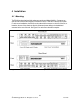
Table of Contents 1 2 3 4 5 6 7 Table of Figures ...................................................................................................................... 4 Table of Tables........................................................................................................................ 4 Product Overview .................................................................................................................... 6 3.1 Functional Overview.........................................
1 Table of Figures Figure 1: RS416 LED Display Panel ............................................................................................... 8 Figure 2: RS416 Series Rack mount chassis orientation options – Front and rear mount. ............ 10 Figure 3: 19” Rack Mount Adapters .............................................................................................. 11 Figure 4: Rack mount adapter mounting location..........................................................................
Table 13: Type Test Specification - Electrical Safety ..................................................................... 33 Table 14: Type Test Specification - Electrical Environment ........................................................... 33 Table 15: Type Test Specification - Atmospheric Environment ...................................................... 33 Table 16: Operating Environment ..................................................................................................
3 Product Overview 3.1 Functional Overview The RuggedServer™ RS416 is an industrially hardened serial device server with an integrated, fully managed, Ethernet switch, designed to operate reliably in electrically harsh and climatically demanding environments. Featuring a modular design that can support up to 16 serial ports and up to 4 Ethernet ports, the RS416 is able to interconnect multiple types of intelligent electronic devices (IEDs) that have different methods of communications.
• • • • • Integrated Ethernet Switch - 2 or 4 port options (copper and/or fiber) High performance and throughput Ethernet switching Fully IEEE 802.3, IEEE 802.3u, IEEE 802.
3.3 Display Panel Description The RS416 is equipped with a versatile display panel, shown in Figure 1, which is designed to provide quick status information for each port, as well as the entire device to allow for simple diagnostics and troubleshooting. It features: • • • • RS232 console port for ‘out of band’ console access and configuration Power supply and Alarm status indicators Convenient port status indicators conveying Link-Activity, Duplex, or Speed via pushbutton control.
The port-based LEDs can be cycled between three display modes: Status, Duplex, and Speed. Pushing the mode button causes the display mode to be cycled. Table 2 and Table 3 define the possible port LED colours and the corresponding description.
4 Installation 4.1 Mounting The RS416 has been designed with maximum mounting and display flexibility. Customers can order an RS416 that can be mounted in a standard 19” rack, 1” DIN Rail, or directly onto a panel. For rack mount installations, the RS416 can be ordered with connectors on the front of the unit, or located on the rear of the chassis to allow for all data and power cabling to be installed and connected at the rear of the rack. See Figure 2 for rack mount orientation examples.
4.1.1 Rack Mounting The RS416 can be rack mounted using the included rack mount adapter assemblies shown in Figure 3. Secure the one rack mount adapter to the front of each side of the chassis using the included black PAN head Philips screws in the positions shown in Figure 4. The entire chassis can then be mounted to a standard 19” rack. An additional two rack mount adapters are included to optionally secure the rear of the chassis in high-vibration, or seismically active locations.
4.1.2 Panel and DIN Rail Mounting The RS416 can be ordered as a Panel/DIN mount chassis. Both options involve the use of the panel/DIN adapters to be mounted on each side of the chassis enclosure. The adapter allows the chassis to be mounted on the standard 1” DIN rail using the grooves in the adapter, secured using the included Philips screw. See Figure 5 for a PANEL/DIN mount diagram. Figure 5: RS416 Series PANEL/DIN RAIL mounting diagram with 12 2008 RuggedCom Inc.
4.
Terminal # Description Usage PS1 Live / + is connected to the positive (+) terminal if the power source is DC or to the (Live) terminal if the power source is AC. PS1 Surge Ground is connected to the Chassis Ground via a jumper on the terminal block. Surge Ground is used as the 2 PS1 Surge Ground ground conductor for all surge and transient suppression circuitry.
4.2.1 AC Power Supply Wiring Examples Figure 8: AC Power supply wiring examples NOTES: 1. 100-240VAC rated equipment: A 250VAC appropriately rated circuit breaker must be installed within 3m of unit. 2. Equipment must be installed according to the applicable country wiring codes. 3. When equipped with two HI voltage power supplies, independent AC sources can be used to power the product for greater redundancy.
4.2.2 DC Power Supply Wiring Examples Figure 9: DC Power supply wiring examples NOTES: 1. 88-300VDC rated equipment: A 300VDC appropriately rated circuit breaker must be installed within 3m of unit. 2. A circuit breaker is not required for 12, 24 or 48 VDC rated power supplies. 3. Equipment must be installed according to the applicable country wiring codes. 4. When equipped with two HI voltage power supplies, independent AC sources can be used to power the product for greater redundancy.
4.2.3 Dual Power Supplies Wiring Examples Figure 10: DC And AC power supply wiring examples NOTES: 1. 88-300VDC rated equipment: A 300VDC appropriately rated circuit breaker must be installed within 3m of unit. 2. 100-240VAC rated equipment: A 250VAC appropriately rated circuit breaker must be installed within 3m of unit. 3. A circuit breaker is not required for 12, 24 or 48 VDC rated power supplies. 4. Separate circuit breakers must be installed and separately identified. 5.
4.3 Dielectric Strength (HIPOT) Testing For dielectric strength (HIPOT) testing in the field, users must remove the metal jumper located on terminal 2, 4, and 6 of the power supply terminal block. This metal jumper connects transient suppression circuitry to chassis ground and must be removed in order to avoid damage to transient suppression circuitry during HIPOT testing. Figure 11 shows the proper HIPOT test connections and should be followed to avoid damage to the device.
4.4 Failsafe Alarm Relay Wiring The “Failsafe” output relay is provided to signal critical error conditions that may occur on the RS416. The contacts are energized upon power up of the unit and remain energized until a critical error occurs. The proper relay connections are shown in Figure 12. One common application for this output is to signal an alarm if a power failure or removal of control power occurs.
4.5 Console Port Wiring A RS232 console port for configuration and management of the device is located on the LED display module shown in Figure 13. This port is intended to be a temporary connection during initial configuration or troubleshooting and allows for direct access to the serial-based management console. The connection is made using the DB9-Female to RJ45 console cable included in the device packaging shown below.
4.6 Serial Ports The RS416 can be equipped with a Fiber Serial Interface, RS232/RS485/RS422 DB9 serial ports or RS232/RS485/RS422 RJ45 serial ports. 4.6.1 Fiber Serial Interface The RS416 can be equipped with a Fiber Serial Interface (ST connector only) which allows RS485, RS422, or RS232 devices to communicate over secure, noise immune, optically isolated, fiber optic cabling at extended distances as well as protocol independent conversion to multimode fiber optics.
4.6.2 RS232/RS485/RS422 via DB9 Each port is individually selectable via software to be RS232, RS485 or RS422. The DB9 port and pin-out is shown below. Figure 16: DB9 Female DCE Port pin-out Pin 1 2 3 4 5 6 7 8 RS232 Mode CD TX RX DTR DSR CTS RTS RI (No Connection) RS485 Mode TX/RX+ - Common (Isolated Ground) TX/RX - 9 Shield Chassis Ground Table 5: DB9 Female DCE Port pin-out RS422 Mode TX+ RX+ RXTX- - NOTES: 1. No internal termination is provided. 2. Pins 1, 4, and 6 are connected internally.
4.6.3 RS232/RS485/RS422 via RJ45 Each port is individually selectable via software to be RS232, RS485 or RS422. The RJ45 port and pin-out is shown below. Figure 17: RJ45 Port pin-out Pin RS232 Mode RS485 Mode RS422 Mode 1 DSR RX2 DCD 3 DTR 4 Common (Isolated Ground) 5 RX RX+ 6 TX TX/RX + TX + 7 CTS 8 RTS TX/RX TX Shield Chassis Ground Table 6: RJ45 Port pin-out NOTES: 1. No internal termination is provided. 2. Pins 1, 2, and 3 are connected internally. Pins 7 and 8 are connected internally.
4.6.4 RS485 Wiring Each RS485 port can communicate to multiple RS485 devices by daisy chaining devices over a single twisted pair with transmit and receive signals on the same two wires (half duplex). The following guidelines should be followed to ensure reliable continuous communication: 1. To minimize the effects of ambient electrical noise, shielded cabling is recommended. 2. The correct polarity must be observed throughout a single daisy chain. 3.
4.6.5 Serial Port Transient Protection RuggedCom does not recommend the use of copper cabling of any length for critical real-time substation automation applications. However, transient suppression circuitry is present on all copper ports to protect against damage from electrical transients and to ensure IEC 61850-3 and IEEE 1613 Class 1 conformance. This means that during the transient event communications errors or interruptions may occur but recovery is automatic.
4.7 Ethernet Ports 4.7.1 Copper Ports The RS416 may have up to 4 10/100BaseTX ports that allow connection to standard CAT-5 UTP cable with RJ45 male connectors. All RJ45 Ethernet ports feature auto-negotiating, auto-polarity, and auto-crossover functions. The RJ45 receptacles can also accept and take advantage of screened (commonly known as “shielded”) cabling. Figure 19 shows the RJ45 port pins configuration.
4.7.2 Fiber Optic Ports Depending on the order code of the product, the RS416 can be equipped with several different types of fiber optic ports. The Transmit (TX) and Receive (RX) connections of each port must be properly connected and matched for proper link and operation. Modules populated on the top row of the device typically have locking mechanisms or tabs towards the top of the unit. Modules located on the bottom row of the device have locking mechanisms or tabs towards the bottom of the device.
4.7.3 Ethernet Panel Description Each Ethernet module is equipped with two LEDs that indicate link/activity status information. The LED will be solid for ports with link, and will blink for activity. The diagram in Figure 25 highlights the port and the associated link/activity LED. Figure 25: Ethernet panel LED description 28 2008 RuggedCom Inc.
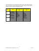
5 Technical Specifications 5.1 Power Supply Specifications Power Supply Input Range Type Min Max 12 – 24 VDC 10 VDC 36 VDC 24 VDC 18 VDC 36 VDC 48 VDC 36 VDC 59 VDC HI (125/250 VDC) 1 88 VDC 300 VDC HI (110/230 VAC) 1 85 VAC 265 VAC Table 7: Power Supply Specifications Fuse Rating 6.3A(F) 2 5A(F) 2 2A(T) 2 Max. Power Consumption3 15 W 2A(T) 1,2 NOTES: 1. This is the same power supply for both AC and DC. 2. (F) Denotes fast-acting fuse, (T) denotes time-delay fuse 3.
5.3 Data Port Specifications 5.3.1 Serial Ports 5.3.1.1 Copper Ports Parameter Specifications Notes Baud Rate Connector 300 bps – 230 kbps DB9 or RJ45 RMS 1-minute Isolation 2.5 kV Table 9: Copper Port Specification 5.3.1.2 Fiber Optic Ports Parameter Specifications Mode Multimode Connector ST Typical Dist. (km) 5 Optical Wavelength (nm) 820 Cable Size 50/125 Core/Cladding (um) 62.5/125 Table 10: Fiber Optic Port Specification NOTES: 1.
5.3.2 Ethernet Ports 5.3.2.1 Copper Ports Parameter Specification Speed 10/100 Mbps Duplex FDX / HDX Cable-Type > Category 5 Wiring Standard TIA/EIA T568A/B Max Distance 100 m Connector RJ45 Isolation 1.5 kV Table 11: Ethernet Ports - Copper Specifications Notes Auto-negotiating Auto-negotiating Shielded/Unshielded Auto-Crossover, Auto-polarity RMS 1-minute 5.3.2.2 Fiber Optic Ports The following sections detail fiber optic specifications on ports that can be ordered with the RS416.
NOTES: 1. Maximum segment length is greatly dependent on factors such as fiber quality, and number of patches and splices. Please consult RuggedCom sales associates when determining maximum segment distances. 2. All optical power numbers are listed as dBm averages. 3. All cabling is duplex type unless otherwise specified. 4. These transceivers utilize a distributed feedback (DFB) type laser and are rated for -20°C to +85°C operation only. 32 2008 RuggedCom Inc.
5.4 Type Test Specifications Electrical Safety Levels Dielectric Withstand 2 kV rms for 1 minute High Voltage Impulse 5 kV peak Insulation Resistance 500 VDC for 1 minute Table 13: Type Test Specification - Electrical Safety Electrical Environment High Frequency Disturbance (Oscillatory) Levels 2.
5.5 Operating Environment Parameter Range Ambient Operating Temperature -40 to 85°C Ambient Relative Humidity Ambient Storage Temperature Table 16: Operating Environment 5% to 95% Comments Ambient Temperature as measured from a 30cm radius surrounding the center of the RS1600 enclosure. Non-condensing -40 to 85°C 5.6 Mechanical Specifications Parameter Value Dimensions 18.29 x 10.17 x 1.
Figure 26: Mechanical Drawing 35 2008 RuggedCom Inc.
6 Agency Approvals Agency Standards CSA CSA C22.2 No. 60950, UL 60950 CE EN 60950, EN 61000-6-2 FCC FCC Part 15, Class A CISPR EN55022, Class A FDA/CDRH 21 CFR Chapter 1, Subchapter J IEC/EN EN60825-1:1994 + A11:1996 + A2:2001 Table 18: Agency Approvals Comments Approved Approved Approved Approved Compliant Compliant 7 Warranty RuggedCom warrants this product for a period of five (5) years from date of purchase. For warranty details, visit http://www.ruggedcom.