RuggedSwitch RuggedSwitch RS500 Installation Guide RuggedCom Inc. 30 Whitmore Road, Woodbridge, Ontario Canada L4L 7Z4 Web: www.ruggedcom.
Federal Communications Commission Radio Frequency Interference Statement This equipment has been tested and found to comply with the limits for a Class A digital device pursuant to Part 15 of the FCC Rules. These limits are designed to provide reasonable protection against harmful interference when the equipment is operated in a commercial environment.
Table of Contents 1 Product Overview.....................................................................................................................4 1.1 Functional Overview............................................................................................... 4 1.2 Feature Highlights.................................................................................................. 4 1.3 RS500 Front Panel Description ..............................................................................
1 Product Overview 1.1 Functional Overview The RuggedSwitch RS500 is a substation hardened, fiber optical Ethernet switch specifically designed to operate in harsh environments such as those found in electric utility substations and harsh industrial environments. The RS500 provides 4 10BaseFL fiber optical ports and one 100BaseFX port. Specifically tested to the same standards as mission critical protective relaying equipment (i.e. ANSI/IEEE C37.
1.3 RS500 Front Panel Description Front Panel View 10BaseFL Ports ST Connectors 100BaseFX Port MTRJ Connector LED Indicators LINK/Activity Rx (Receive) Tx (Transmit) POWER LED Failsafe Output Relay Power DC(+) DC(-) Surge Ground Normally Open Common Reset Safety Ground Stud Normally Closed Fig. 1.3.
1.4 RS500 Top and Bottom View Top View DIN Rail Mounting Bracket 10BaseFL Ports ST Connectors Safety Ground Stud Bottom View DC(-) Reset Failsafe Output Relay DC(+) Surge Ground 100BaseFX Port MTRJ Connector DIN Rail Mounting Bracket Fig. 1.4.1 RS500 Top and Bottom View 6 2008 RuggedCom Inc.
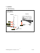
2 Installation 2.1 DIN Rail Mounting RS500 DIN Rail Mounting & Release Front View Side View DIN RAIL DIN RAIL Mounting Latch DIN RAIL Release Slot Release Direction Screw Driver Release Action Fig. 2.1.1 RS500 Rail Mounting 7 2008 RuggedCom Inc.
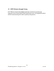
2.2 Power Supply Wiring and Grounding Safety Ground Stud DC(+) DC(-) Surge Ground Fig. 2.2.1 RS500 Power Supply Inputs The power supply input is connected as follows: 1. + = DC (+) is connected to the positive (+) terminal if the power source is DC or to the (Hot) terminal if the power source is AC. 2. - = DC (-) is connected to the negative (-) terminal if the power source is DC or to the (Neutral) terminal if the power source is AC. 3.
2.2.1 Power Supply - DC Input Fig. 2.2.2 Power Supply – DC Input Note: Ground bus can either be connected to the Ground Stud on the rear of the RS500 chassis, or the Surge Ground port on the screw-in terminal block. 9 2008 RuggedCom Inc.
2.3 HIPOT (Dielectric Strength) Testing HIPOT Dielectric strength testing cannot be performed in the field due to transient/surge suppression circuitry connected to the RS500 Surge/Chassis Ground. All RuggedSwitch products are HIPOT tested according to IEC 60255-5 (Section 6) during final test. 10 2008 RuggedCom Inc.
2.4 Failsafe Output Wiring and Specifications The “Failsafe” output relay is provided to signal critical error conditions that may occur on the RS500. The contacts are energized upon power up of the unit and remain energized until a critical error occurs. RS500 Failsafe Relay Outputs Normally Closed Common Normally Open *** Normal contact state prior to power being applied to unit. *** 11 2008 RuggedCom Inc.
3 Technical Specifications 3.1 Power Supply Specifications Power Supply Type 24 VDC 48 VDC HI (110 VDC) Minimum Input 18 VDC 36 VDC 88 VDC Maximum Input 36 VDC 59 VDC 150 VDC Fuse Rating Maximum Power Consumption 5A(F) 3.15A(T) 3.15A(T) 10 W NOTES: 1. (T) denotes time-delay fuse 2. For continued protection against risk of fire, replace only with same type and rating of fuse. 3.2 Failsafe Relay Specifications Parameter Max Switching Voltage Rated Switching Current Value (Resistive) 30VAC, 80VDC 0.
3.4 Fiber Optical Specifications Ports 1 to 4 10Mbps Ports Parameter Multi-Mode Speed Standard Connector Type Segment Length Optical Wavelength Cable Size Core/Cladding Optical Tx Power Min/Max (dBm Peak) Optical Rx Sensitivity (dBm Average) Max Optical Rx Power (dBm Peak) Typical Optical Power Budget (dB) * Available as an option Uplink 100Mbps Port Single-Mode* 10BaseFL ST Multi-Mode Single-Mode* 100BaseFX MTRJ LC 2 km 15 km 1300nm 1310nm 2 km 820nm 15 km 1310nm 62.5/125µm 9/125µm 62.
3.6 Type Test Specifications Electrical Safety Dielectric Withstand Levels 2 kV rms for 1 minute High Voltage Impulse Insulation Resistance 5 kV peak 500 VDC for 1 minute Electrical Environment High Frequency Disturbance (Oscillatory) IEC Surge Levels 2.
3.7 Operating Environment Parameter Ambient Operating Temperature Range -40 to 85°C Ambient Relative Humidity Ambient Storage Temperature 5% to 95% -40 to 85°C Comments Ambient Temperature as measured from a 30cm radius surrounding the center of the R500 enclosure. Non-condensing 3.8 Physical Dimensions 15 2008 RuggedCom Inc.
Parameter Dimensions Value 8.0 x 6.84 x 2.43 inches (203,20) x (173,74) x (61,72) mm Weight Enclosure Comments (Length x Width x Height) with mounting brackets installed 5 lb (2.25 Kg) 18 gauge Galvanized Steel 3.9 Agency Approvals Agency cCSAus, CE FCC Standards CSA C22.2 No. 60950, UL 60950, EN 60950 EN 61000-6-2 FCC Part 15, Class A Comments Approved Approved 4 Warranty RuggedCom warrants this product for a period of five (5) years from date of purchase. For warranty details, visit http://www.