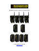
RS900 Series Family of Switches Installation Guide www.ruggedcom.
Copyright This document contains proprietary information, which is protected by copyright. No part of this document may be photocopied, reproduced or translated to another language without the prior written consent of RuggedCom Inc. Disclaimer RuggedCom has checked the contents of this manual against the hardware and software described. However, deviations from the description cannot be completely ruled out.
Table of Contents 1 2 3 4 Product Overview ................................................................................................................................................... 6 1.1 Functional Overview ................................................................................................................... 6 1.2 RuggedSwitch .............................................................................................................................. 7 1.
RS900 Family Installation Guide 7.2 IEEE 1613 Type Tests ............................................................................................................... 42 7.3 IEC Environmental Type Tests .................................................................................................. 42 Page 4 of 42 © 2008 RuggedCom Inc. All rights reserved.
RS900 Family Installation Guide Table of Figures Figure 1 - Front Panel Description ........................................................................................................... 13 Figure 2 - Bottom Panel Description......................................................................................................... 14 Figure 3 - DIN Rail Mounting ...................................................................................................................
RS900 Family Installation Guide 1 Product Overview 1.1 Functional Overview The RS900 family of switches are environmentally hardened, fully managed switches supporting a variety of Ethernet interfaces including copper, fiber, wireless as well as Serial communications.
RS900 Family Installation Guide 1.2 RuggedSwitch RS900 9 Port Fiber Optic Ethernet Switch • • Up to 9 fast Ethernet ports Copper and fiber options Page 7 of 42 © 2008 RuggedCom Inc. All rights reserved.
RS900 Family Installation Guide 1.3 RuggedWireless Family of Products Wireless Port Characteristics • • • • • • Configurable as an access, client, or bridge device IEEE 802.11b/g Wireless Access Point with data rates up to 54 Mbps WPA (Wi-Fi Protected Access) with TKIP for enhanced security and encryption WPA2 / 802.11i with CCMP for robust security and encryption IEEE 802.
RS900 Family Installation Guide RS920W RS930W Wireless Serial Device Server with 2 Serial Ports and 1 Ethernet over VDSL Interface Wireless Ethernet with Integrated 6-Port Switch and 1 Ethernet over VDSL Interface • • • 1 Wireless interface 1 EoVDSL interface 2 RS485/RS422/RS232 Serial ports (DB9 or RJ45); Serial Fiber interface (ST) available • • • 1 Wireless interface 1 EoVDSL interface 6 fast Ethernet ports Port 9 Antenna #1 Port 7 Ethernet over VDSL Ports 1 & 2 Serial Power & Alarm Port 9 Ant
RS900 Family Installation Guide 1.4 RuggedVDSL Family of Products EoVDSL Port Characteristics • • • • Symmetric data rates up to 35 Mbps with distances up to 2.
RS900 Family Installation Guide RS920L RS930L Dual Ethernet over VDSL interfaces with integrated Dual Port Serial Server Dual Ethernet over VDSL interfaces with Integrated 6-Port Switch • • 2 EoVDSL interfaces 2 RS485/RS422/RS232 Serial ports (DB9 or RJ45); Serial Fiber interface (ST) available Port 3 Ethernet over VDSL • • 2 EoVDSL interfaces 6 fast Ethernet ports Port 9 Ethernet over VDSL Ports 1 & 2 Serial Power & Alarm Page 11 of 42 © 2008 RuggedCom Inc. All rights reserved.
RS900 Family Installation Guide 1.5 RuggedServer RS910 2-Port Serial Device Server with up to 3 Ethernet Ports • • • 2 RS485/RS422/RS232 Serial ports (DB9 or RJ45); Serial Fiber interface (ST) available Up to 3 fast Ethernet ports Copper and fiber options Page 12 of 42 © 2008 RuggedCom Inc. All rights reserved.
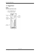
RS900 Family Installation Guide 1.6 Front Panel Description Power, Alarm & Reset Port 9 10/100Base-TX or 100Base-Fx Ports 3 & 4 10/100Base-TX or 100Base-FX Ports 1-6 10/100Base-TX Figure 1 - Front Panel Description Status LED Power LED Alarm LED Colour Green Red Activity Solid Solid Comments Power On Alarm condition exists Table 1 - Status LEDs Page 13 of 42 © 2008 RuggedCom Inc. All rights reserved.
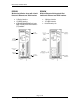
RS900 Family Installation Guide 1.7 Bottom Panel Description Console Port Chassis Ground Power Port Failsafe Relay Optional Din-Rail Mounting Bracket Figure 2 - Bottom Panel Description Page 14 of 42 © 2008 RuggedCom Inc. All rights reserved.
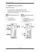
RS900 Family Installation Guide 2 Installation 2.1 Din Rail Mounting An optional DIN rail-mounting bracket is available for the unit. The figure below details mounting instructions for the standard 1” DIN Rail. Figure 3 - DIN Rail Mounting Page 15 of 42 © 2008 RuggedCom Inc. All rights reserved.
RS900 Family Installation Guide 2.2 Power Supply Wiring and Grounding 2.2.1 AC Power Supply Wiring and Grounding AC Surge Line/Hot Ground AC Neutral Chassis Ground Figure 4 - Power Supply Inputs The AC power supply inputs should be connected as follows: 1. +/L should be connected to AC Line/Hot. 2. -/N should be connected to AC Neutral. 3. Surge Ground should be connected to the Chassis Ground via a braided cable or other appropriate grounding wire.
RS900 Family Installation Guide 2.2.2 DC Power Supply Wiring and Grounding Figure 5 - DC Power supply wiring and grounding diagram The low voltage DC power supply features reverse polarity protection and dual independent inputs. The latter feature allows the connection of two DC sources with the same nominal voltage to provide redundant power supply inputs. The DC power supply inputs should be connected as follows: 1. Connect to the DC inputs according to the polarity markings on the unit. 2.
RS900 Family Installation Guide 2.2.3 Failsafe Output Wiring The Failsafe output relay is provided to signal critical error conditions that may occur on the unit. The contacts are energized upon power up of the unit and remain energized until an alarm condition or power loss occurs. Figure 6 - Failsafe Output Relay Page 18 of 42 © 2008 RuggedCom Inc. All rights reserved.
RS900 Family Installation Guide 2.2.4 Dielectric Strength Testing Units which are to have dielectric strength testing (HIPOT testing) done in the field must have the braided ground cable disconnected during the test. This is required in order to prevent the surge suppression circuitry, which is connected to surge ground, from being activated. Figure 7 - Dielectric Strength Testing Page 19 of 42 © 2008 RuggedCom Inc. All rights reserved.
RS900 Family Installation Guide 2.3 RS232 Console Port Wiring The RS232 port is used for configuring the unit. A straight-through serial cable with a DB-9 connector is required. There is no need to crossover the Transmit and Receive signals from the PC side since this has been done internally.
RS900 Family Installation Guide 3 Ethernet Ports 3.1 RJ11 Ethernet over VDSL Port 3.1.1 Overview The Ethernet over VDSL (EoVDSL) port operates in pairs with one unit configured as the Master and the other as the Slave. In VDSL literature the terms Central Office (CO) or Line Termination (LT) are used interchangeably for the Master and the terms Customer Premise Equipment (CPE) or Network Termination (NT) are used interchangeably for the Slave.
RS900 Family Installation Guide 3.1.3 RJ11 Port EoVDSL data ports allow connection using RJ11 male connectors. The figure below shows the RJ11 port pin-out and LEDs. On units with Universal EoVDSL ports the Master LED can be toggled on or off depending on whether the port is set as a Master or Slave. On units with Long-Reach EoVDSL ports the Master unit will have the LED permanently on while the Slave unit will have the LED permanently off.
RS900 Family Installation Guide 3.1.5 Performance The EoVDSL ports can be configured in two modes – Auto Mode and Manual Mode. In Auto Mode, which is the default mode, the unit will step through the different speeds and automatically select the best bit-rate based on current line conditions. In Manual Mode the user can select one of the speed settings and the unit will only attempt to attain the set speed.
RS900 Family Installation Guide NOTES: 1. The EoVDSL ports are designed to be used on private communications lines for point-to-point connections and are not to be connected to the Public Switched Telephone Network (PSTN). 2. To reduce the risk of fire, use only No. 26 AWG or larger telecommunication line cord. 3. In Manual Mode, assuming the distance can support the speed setting; the time to port up is typically 15-30 seconds. Page 24 of 42 © 2008 RuggedCom Inc. All rights reserved.
RS900 Family Installation Guide 3.2 RJ45 Ethernet Port Units with 10/100Base-TX ports allow connection to standard Category 5 (CAT-5) unshielded twisted-pair (UTP) cable with RJ45 male connectors. The RJ45 receptacles are directly connected to the chassis ground on the unit and can accept CAT-5 shielded twisted-pair (STP) cables. If shielded cables are used, care must be taken to ensure the shielded cables do not form a ground loop via the shield wire and the RJ45 receptacles at either end.
RS900 Family Installation Guide 3.3 Fiber Optic Ethernet Port Depending on the order code of the product, the unit can be equipped with several different fiber optic ports. The Transmit (Tx) and Receive (Rx) connections of each port must be properly connected and matched for proper link and operation. The drawings in the following figures show each fiber optical connector style with a side and top view to allow the user to identify the proper cable connection orientation.
RS900 Family Installation Guide 3.4 Wireless Ethernet Port Refer to the “RuggedCom Wireless Guide” for an introduction to 802.11 Ethernet-based wireless technologies as well as answers to frequently asked questions. Refer to the “Rugged Operating System (ROS) User Guide” for instructions on wireless port configuration. Both of the above documents can be downloaded from the following webpage: http://www.ruggedcom.com/products/ruggedwireless/rs900w Page 27 of 42 © 2008 RuggedCom Inc. All rights reserved.
RS900 Family Installation Guide 4 Serial Ports Serial ports can be either DB9 Serial ports, RJ45 serial ports or Fiber Serial ports 4.1 DB9 Serial Port The DB9 port is selectable via software to be RS232, RS485 or RS422. Figure 15: DB9 Female DCE Port pin-out Pin 1 2 3 4 5 6 7 8 9 Shield RS232 Mode DCD TX RX DTR RS485 Mode TX/RX+ - Common (Isolated Ground) DSR CTS TX/RX RTS RI (No Connection) Chassis Ground RS422 Mode TX+ RX+ RXTX- Table 9: DB9 Female DCE Port pin-out NOTES: 1.
RS900 Family Installation Guide 4.2 RJ45 Serial Port The RJ45 Serial port is selectable via software to be RS232, RS485 or RS422. Figure 16: RJ45 Port pin-out Pin 1 2 3 4 5 6 7 8 Shield RS232 Mode RS485 Mode RS422 Mode DSR RXDCD DTR Common (Isolated Ground) RX RX+ TX TX/RX + TX + CTS RTS TX/RX TX Chassis Ground Table 10: RJ45 Port pin-out NOTES: 1. No internal termination is provided. 2. Pins 1, 2, and 3 are connected internally. Pins 7 and 8 are connected internally.
RS900 Family Installation Guide 4.3 Fiber Serial Port The Fiber Serial Interface (ST connector only) which allows RS485, RS422, or RS232 devices to communicate over secure, noise immune, optically isolated, fiber optic cabling at extended distances as well as protocol independent conversion to multimode fiber optics. Figure 17: Fiber Serial Interface (ST Connector) Page 30 of 42 © 2008 RuggedCom Inc. All rights reserved.
RS900 Family Installation Guide 4.4 RS485 Wiring Each RS485 port can communicate to multiple RS485 devices by daisy chaining devices over a single twisted pair with transmit and receive signals on the same two wires (half duplex). The following guidelines should be followed to ensure reliable continuous communication: 1. To minimize the effects of ambient electrical noise, shielded cabling is recommended. 2. The correct polarity must be observed throughout a single daisy chain. 3.
RS900 Family Installation Guide 5 Transient Protection RuggedCom does not recommend the use of copper cabling of any length for critical real-time substation automation applications. However, transient suppression circuitry is present on all copper ports to protect against damage from electrical transients and to ensure IEC 61850-3 and IEEE 1613 Class 1 conformance. This means that during the transient event communications errors or interruptions may occur but recovery is automatic.
RS900 Family Installation Guide 6 Technical Specifications 6.1 Operating Environment Parameter Range Ambient Operating Temperature -40 to 85°C Ambient Storage Temperature Ambient Relative Humidity -40 to 85°C 5% to 95% Comments Ambient Temperature as measured from a 30 cm radius surrounding the center of the enclosure. Non-condensing Table 11 - Operating Environment 6.
RS900 Family Installation Guide Isolation Comments 1500 Vrms Dielectric test voltage (1 minute) between coil & contacts Table 14 - Failsafe Relay Isolation 6.4 Ethernet Ports Specifications 6.4.1 RJ11 Ethernet over VDSL Port Specifications Data Port Media Distance Connector Type EoVDSL CAT-3 UTP or STP 2500m RJ11 Table 15 – RJ11 Ethernet over VDSL Port Specifications 6.4.
RS900 Family Installation Guide 6.4.3 Fiber Optic Ethernet Port Specifications Cable Type (um) Tx min (dBm) Tx max (dBm) Rx Sensitivity (dBm) Rx Saturation (dBm) Typical Distance (km) Power Budget (dB) 1300 50/125 62.5/125 -22.5 -19 -14 -14 -33.5 -33.5 -14 -14 2 2 11 14.5 MM/SC 1300 50/125 62.5/125 -22.5 -19 -14 -14 -33.9 -33.9 -14 -14 2 2 11.4 14.9 100FX MM/ST 1300 50/125 62.5/125 -22.5 -19 -14 -14 -33.9 -33.9 -14 -14 2 2 11.4 14.9 ML 100FX MM/LC 1310 62.
RS900 Family Installation Guide 6.4.4 Communication Standards Protocol Ethernet VDSL Standards IEEE 802.3 ETSI TS 101 270-2 V1.1.1, ITU-T G.993.1, ANSI T1E1.4 Table 18 - Communication Standard Compliance Page 36 of 42 © 2008 RuggedCom Inc. All rights reserved.
RS900 Family Installation Guide 6.5 Wireless Ethernet Port Specification 6.5.1 Wireless Standards Supported Standard Parameter Mode Notes IEEE 802.11g 54 Mbps (WLAN) Full Access Point 2.4 GHz ISM IEEE 802.11b 11 Mbps (WLAN) Client support Backwards compatibility IEEE 802.
RS900 Family Installation Guide 6.5.3 Channel Allocations for IEEE 802.11b/g The channel identifiers, channel center frequencies, and regulatory domains of each IEEE 802.11b/g 22-MHz-wide channel are shown in the table below.
RS900 Family Installation Guide 6.6 Serial Ports Specifications 6.6.1 DB9 & RJ45 Serial Port Specifications Parameter Specifications Baud Rate 300 bps – 230 kbps Connector DB9 or RJ45 Isolation 2.5 kV Notes RMS 1-minute Table 22: Copper Port Specification 6.6.2 Fiber Serial Port Specifications Parameter Specifications Mode Multimode Connector ST Typical Dist. (km) 5 Optical Wavelength (nm) 820 Cable Size Core/Cladding (um) 50/125 62.
RS900 Family Installation Guide 6.7 Mechanical Specifications Parameter Dimensions Weight Enclosure Value 16.8 x 11.7 x 6.6 cm / 6.6 x 4.6 x 2.6 inches 1.2 kg / 2.7 lbs 20 AWG Galvanized Steel Table 24 - Mechanical Specifications Figure 19 - Mechanical Specifications Page 40 of 42 © 2008 RuggedCom Inc. All rights reserved.
RS900 Family Installation Guide 7 Type Tests 7.1 IEC 61850-3 Type Tests Test Description IEC 61000-4-2 ESD IEC 61000-4-3 Radiated RFI IEC 61000-4-4 Burst (Fast Transient) Test Levels Enclosure Contact Enclosure Air Enclosure ports Signal ports D.C. Power ports A.C. Power ports Earth ground ports Signal ports D.C. Power ports +/- 8kV +/- 15kV 20 V/m +/- 4kV @ 2.
RS900 Family Installation Guide 7.2 IEEE 1613 Type Tests IEEE Test IEEE 1613 Clause C37.90.3 9 ESD C37.90.2 8 Radiated RFI C37.90.1 7 Fast Transient C37.90.1 7 Oscillatory C37.90 6 H.V. Impulse C37.90 6 Dielectric Strength Description Test Levels Enclosure Contact Enclosure Air Enclosure ports Signal ports D.C. Power ports A.C. Power ports Earth ground ports Signal ports D.C. Power ports A.C. Power ports Signal ports D.C. Power ports A.C. Power ports Signal ports D.C. Power ports A.C.