
User's Manual


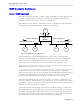
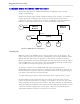
Table Of Contents
- About this User Guide
- Table Of Contents
- Chapter 1– Setting Up And Administering The Switch
- Chapter 2 - Configuring MAC Address Management
- Chapter 3 – Configuring the Ports
- Chapter 4 – Configuring VLANs
- Chapter 5 – Configuring Class of Service
- Chapter 6 – Configuring Rapid Spanning Tree
- Chapter 7 – Configuring Multicast Filtering
- Chapter 8 – Diagnostics
- Chapter 9 – Using Ethernet And RMON Statistics
- Introduction
- View Ethernet Statistics
- View Ethernet Port Statistics
- Remote Monitoring (RMON)
- RMON Historical Statistics Concepts And Issues
- RMON Alarms And Events Concepts And Issues
- The Alarm Process
- Alarm Generation And Hysteresis
- Delta vs. Absolute Values
- Configure RMON Alarms
- Configure RMON Events
- RMON Event Logs
- Troubleshooting
- Chapter 10 - Using The CLI Shell
- Chapter 11 – Upgrading Firmware And Managing Configurations
- Appendix A - Menu Tree
- Appendix B - SNMP MIB Support
- Appendix C – SNMP Trap Summary
- Appendix D – RMON Acceptable MIB Parameters
- Index

RuggedSwitch™ User Guide
Combined Router And Switch IGMP Operation
This section describes the additional challenges of multiple routers, VLAN
support and switching.
Producer P1 resides upon VLAN 2 while P2 resides upon VLAN 3. Consumer C1
resides upon both VLANs whereas C2 and C3 reside upon VLANs 3 and 2,
respectively. Router 2 resides upon VLAN 2, presumably to forward multicast
traffic to a remote network or act as a source of multicast traffic itself.
Multicast
Router 1
P1
C1 C2 C3
Switch
Multicast
Router 2
VLAN 2,3 VLAN 3 VLAN 2
VLAN 2
VLAN 2
P2
VLAN 3
VLAN 2
Figure 43: IGMP Operation Example 2
Starting Up
Multicast routers use IGMP to elect a master router known as the querier. All
other routers become of non-queriers, participating only forward multicast traffic.
If both switches and routers are present, a router always becomes the querier.
Routers and switches can always distinguish each other from the source IP address
in the IGMP query. A router uses its own source address while the switch always
uses an address of 0.0.0.0 for queries, joins and leaves.
At startup a switch in active IGMP mode will begin generating general
membership queries for each VLAN on each port every switch query interval. If
the switch detects a querier router on a particular VLAN it will stop generating its
own queries and relay those from the querier.
A switch starting up in passive mode will simply wait for queries from a router.
In this example we will assume that the two routers agree that router 1 is the
querier for VLAN 2 and router 2 is simply a non-querier. In this case, the switch
will periodically receive queries from router 1 and, thus, maintain the information
which port links the multicast router. However, the switch port that links to router
2 must be manually configured as “router port”, otherwise, the switch will not
send neither multicast streams or joins/leaves to router 2.
RuggedCom