RuggedSwitch® RSG2100P Modular Power over Ethernet Managed Ethernet Switch Installation Guide August 14, 2008 www.ruggedcom.com RuggedCom Inc.
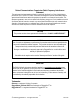
Federal Communications Commission Radio Frequency Interference Statement This equipment has been tested and found to comply with the limits for a Class A digital device pursuant to Part 15 of the FCC Rules. These limits are designed to provide reasonable protection against harmful interference when the equipment is operated in a commercial environment.
Table of Contents 1 2 3 4 5 6 7 8 Table of Figures ...................................................................................................................... 4 Table of Tables ........................................................................................................................ 4 Product Overview .................................................................................................................... 6 3.1 Functional Overview.....................................
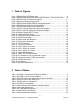
1 Table of Figures Figure 1: RSG2000 Series LED Display Panel ................................................................................ 8 Figure 2: RSG2000 Series Rack mount chassis orientation options – Front and rear mount..........10 Figure 3: RSG2000 Series 19” Rack Mount Adapters.....................................................................11 Figure 4: Rack mount adapter mounting location............................................................................
Table 12: Twisted-Pair Port Specifications......................................................................................29 Table 13: Fast Ethernet optical specifications.................................................................................31 Table 14: Gigabit Ethernet optical specifications.............................................................................32 Table 15: Test Type Specifications .......................................................................................
3 Product Overview 3.1 Functional Overview The RuggedSwitch® RSG2100P is an industrially hardened, Power Over Ethernet (PoE) enabled, fully managed, modular, Ethernet switch specifically designed to operate reliably in electrically harsh and climatically demanding utility substation and industrial environments.
• • • VLAN (802.
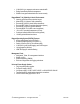
3.3 Display Panel Description The RSG2000 series products are equipped with a versatile display panel, shown in Figure 1, which is designed to provide quick status information for each port, as well as the entire device to allow for simple diagnostics and troubleshooting. It features: • • • • RS232 console port for ‘out of band’ console access and configuration Power supply and Alarm status indicators Convenient port status indicators conveying Link-Activity, Duplex, or Speed via pushbutton control.
The port-based LEDs can be cycled between three display modes: Status, Duplex, and Speed. Pushing the mode button causes the display mode to be cycled. Table 2 defines the possible port LED colours and the corresponding description.
4 Installation 4.1 Mounting The RSG2000 series of products have been designed with maximum mounting and display flexibility. Customers can order an RSG2000 series switch that can be mounted in a standard 19” rack, 1” DIN Rail, or directly onto a panel. For rack mount installations, the RSG2000 series can be ordered with connectors on the front of the unit, or located on the rear of the chassis to allow for all data and power cabling to be installed and connected at the rear of the rack.
4.1.1 Rack Mounting Figure 3: RSG2000 Series 19” Rack Mount Adapters Figure 4: Rack mount adapter mounting location The RSG2000 series family of products can be rack mounted using the included rack mount adapter assemblies shown in Figure 3. Secure the one rack mount adapter to the front of each side of the chassis using the included black PAN head Philips screws in the positions shown in Figure 5. The entire chassis can then be mounted to a standard 19” rack.
4.1.2 Panel and DIN Rail Mounting The RSG2000 series products can be ordered as a Panel/DIN mount chassis. Both options involve the use of the panel/DIN adapters to be mounted on each side of the chassis enclosure. The adapter allows for the chassis to be mounted on the standard 1” DIN rail using the grooves in the adapter, secured using the included philips screw. See Figure 5 for a PANEL/DIN mount diagram. Figure 5: RSG2000 Series PANEL/DIN RAIL mounting diagram with 12 © 2008 RuggedCom Inc.
4.
The RSG2100P can be equipped with either a Philips Screw Terminal Block or a Phoenix Plug Terminal Block. The Philips Screw Terminal Block has Philips screws with a compression plate allowing either bare wire connections or crimped terminal lugs. We recommend the use of #6 size ring lugs to ensure secure, reliable connections under severe shock or vibration. Both terminal blocks have a safety cover which must be removed via two Phillips screws before connecting any wires.
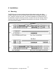
4.2.1 AC Power Supply (PS1) Wiring Example Figure 9: AC (PS1) & 48VDC (PS2) power supply wiring examples NOTES: 1. 100-240VAC rated equipment: A 250VAC appropriately rated circuit breaker must be installed. 2. Equipment must be installed according to the applicable country wiring codes. 15 © 2008 RuggedCom Inc.
4.2.2 DC Power Supply (PS1) Wiring Example Figure 10: DC (PS1) & 48VDC (PS2) power supply wiring examples NOTES: 1. 88-300VDC rated equipment: A 300VDC appropriately rated circuit breaker must be installed. 2. A circuit breaker is not required for 12, 24 or 48 VDC rated power supplies. 3. Equipment must be installed according to the applicable country wiring codes. 16 © 2008 RuggedCom Inc.
4.3 Dielectric Strength (HIPOT) Testing For dielectric strength (HIPOT) testing in the field, users must remove the metal jumper located on terminal 2, 4, and 6 of the power supply terminal block. This metal jumper connects transient suppression circuitry to chassis ground and must be removed in order to avoid damage to transient suppression circuitry during HIPOT testing. Figure 11 shows the proper HIPOT test connections and should be followed to avoid damage to the device.
4.4 Failsafe Alarm Relay Wiring The “Failsafe” output relay is provided to signal critical error conditions that may occur on the RSG2000 series switches. The contacts are energized upon power up of the unit and remain energized until a critical error occurs. The proper relay connections are shown in Figure 12. Control of the output is user selectable and can be programmed via the Rugged Operating System (ROS).
4.5 Console Port Wiring A RS232 console port for configuration and management of the device is located on the LED display module shown in Figure 13. This port is intended to be a temporary connection during initial configuration or troubleshooting and allows for direct access to the serial-based management console. The connection is made using the DB9-Female to RJ45 console cable included in the device packaging shown in Figure 14.
5 Ethernet Ports Each Ethernet module is equipped with two LEDs that indicate link/activity status information. The LED will be solid for ports with link, and will blink for activity. The diagram in Figure 15 highlights the port and the associated link/activity LED. Port 1 Port 2 Port 3 Port 4 Figure 15: Ethernet panel LED description 5.1 RJ45 Twisted-Pair Ports 5.1.1 Data Ports The RSG2100P may have several 10/100BaseTX ports that allow connection to standard CAT-5 UTP cable with RJ45 male connectors.
10/100BaseTx Pin-out Pin Description 1 RX + 2 RX 3 TX + 6 TX 4, 5, 7, 9 NC Table 5: RJ45 Ethernet pin-out assignment 5.1.2 Data and Power Ports The RSG2100P comes standard with 4 10/100BaseTX IEEE 802.3af (PoE) compliant Ethernet ports (ports 17 – 20). In addition to the 10/100BaseTX port features, the PoE ports provide nominal 48 VDC at 350 mA (max 15.4W/port), auto-sensing and automatic power off when cables are removed. Table 6 shows the RJ45 PoE pin-out assignment.
5.2 Fiber Optic Ports Depending on the order code of the product, the RSG2000 series products can be equipped with several different types of fiber optic ports. The Transmit (TX) and Receive (RX) connections of each port must be properly connected and matched for proper link and operation. Modules populated on the top row of the device typically have locking mechanisms or tabs towards the top of the unit.
Figure 21: 100FX / 1000LX ST connector Figure 22: 1000LX GBIC Module and SC connector Figure 23: 1000LX SFP (mini-GBIC) Module and LC connector 23 © 2008 RuggedCom Inc.
5.2.1 Gigabit Ethernet 1000Base-Tx Cabling Recommendations The IEEE 802.3ab Gigabit Ethernet standard defines 1000Mbit/s Ethernet communications over distances of up to 100 meters using 4 pairs of category 5 (or higher) balanced unshielded twistedpair cabling.
5.2.2 Pluggable optics – Installation, removal, and precautions The RSG2000 series of products can be ordered with pluggable optic form factors such as SFP (Small Form-factor Pluggable) or GBIC (Gigabit Interface Converter) modules. These modules can be safely inserted and removed while the chassis is powered and operating – this feature is also known as “hot-swappable”. When inserting or removing optics there are several precautions that should be taken. They include: 1.
5.2.2.2 GBIC Module Removal GBIC Modules have two locking latches on either side of the module shown in Figure 25. To remove GBIC module, disconnect any cable and replace with dust cover to protect the optics. User should depress both latches simultaneously and gently pull the module from the chassis. The module should be immediately stored in an ESD-safe environment. Figure 25: Locking latch location on GBIC optical modules 5.2.2.
6 Technical Specifications 6.1 Power Supply Specifications Power Supply Type (PS1) 12 – 24 VDC 24 VDC 48 VDC Input Range Min Max 10 VDC 18 VDC 36 VDC 36 VDC 36 VDC 59 VDC HI (125/250 VDC) 1 88 VDC 300 VDC HI (110/230 VAC) 1 85 VAC 265 VAC Table 8: Power Supply Specifications Power Supply Input Range Type (PS2) Min Max 48 VDC 37 VDC 72 VDC Table 9: PoE Power Supply Specifications Fuse Rating 6.3A(F) 2 5A(F) 2 2A(T) 2 Max.
6.3 Networking Standards Supported Parameter 10Mbps Ports 9 100Mbps Ports 1000Mbps Ports IEEE 802.3 9 IEEE 802.3u IEEE 802.3z IEEE 802.3ab 9 9 IEEE 802.3x 9 9 IEEE 802.1D 9 9 IEEE 802.1Q 9 9 IEEE 802.1p 9 9 IEEE 802.3af Table 11: Networking Standards Supported 9 9 9 9 9 9 Notes 10BaseT / 10BaseFL 100BaseTX / 100BaseFX 1000BaseSX/LX 1000BaseTx Full Duplex Operation MAC Bridges VLAN (Virtual LAN) Priority Levels Power over Ethernet Ports (17 – 20) 28 © 2008 RuggedCom Inc.
6.4 Twisted-Pair Port Specifications Parameter Specification Speed 10/100 Mbps Duplex FDX / HDX Cable-Type > Category 5 Wiring Standard TIA/EIA T568A/B Max Distance 100 m Connector RJ45 Isolation 1.5 kV PoE Voltage 44 – 57 V PoE Current 350 mA Table 12: Twisted-Pair Port Specifications Notes Auto-negotiating Auto-negotiating Shielded/Unshielded Auto-Crossover, Auto-polarity RMS 1-minute PoE Ports 17 – 20 PoE Ports 17 – 20 29 © 2008 RuggedCom Inc.
6.5 Fiber Optical Specifications The following sections detail fiber optical specifications on ports that can be ordered with the RSG2000 series Ethernet switch. The user determines the type of optics at time of ordering, and can determine the modules installed on a particular unit by reading the factory data file via the RuggedSwitch ROSTM user interface.
6.5.1 Fast Ethernet (10/100 Mbps) Optical Specifications The dual-port fast Ethernet optical specifications for RSG2100P ports 1-8 and 13-20 are shown below organized by module order code. Module order codes are contained within each product’s factory data when assembled and configured at the factory. Consult the RuggedCom ROS to determine the optical assemblies installed in a particular product.
6.5.2 Gigabit Ethernet (1000 Mbps) Optical Specifications For maximum flexibility RuggedCom Inc. offers a number of different transceiver choices for Gigabit fiber optical communications. The table below details fiber optic specifications based on the 2-port modules or pluggable transceivers selected at time of ordering.
NOTES: 1. Maximum segment length is greatly dependent on factors such as fiber quality, and number of patches and splices. Please consult RuggedCom sales associates when determining maximum segment distances. 2. All cabling is duplex type unless otherwise specified. 3. All optical power numbers are listed as dBm averages. 4. These transceivers utilize a distributed feedback (DFB) type laser and are rated for -20°C to +85°C operation only. 5.
6.6 Type Test Specifications Electrical Safety Dielectric Withstand Levels 2 kV rms for 1 minute High Voltage Impulse Insulation Resistance 5 kV peak 500 VDC for 1 minute Electrical Environment High Frequency Disturbance (Oscillatory) IEC Surge Levels IEC Fast Transient 4 kV 10 V/m Comments ANSI/IEEE C37.90.1 IEC 60255-22-1 IEC 61000-4-5 (Level 4) IEC 61000-4-4 (Level 4) ANSI/IEEE C37.90.1 IEC 61000-4-3 35 V/m ANSI/IEEE C37.90.2 2.
6.8 Mechanical Specifications Parameter Dimensions Value 18.29 x 10.17 x 1.74 inches (464,57) x (258,32) x (44,20) mm Comments (Length x Width x Height) with mounting brackets installed Weight 10 lb (4.5 Kg) Enclosure 18awg galvanized steel Table 17: Mechanical Specifications Figure 28: Mechanical Specifications 35 © 2008 RuggedCom Inc.
7 Agency Approvals Agency Standards CSA CSA C22.2 No. 60950, UL 60950 CE EN 60950, EN 61000-6-2 FCC FCC Part 15, Class A CISPR EN55022, Class A FDA/CDRH 21 CFR Chapter 1, Subchapter J IEC/EN EN60825-1:1994 + A11:1996 + A2:2001 Table 18: Agency Approvals Comments Approved Approved Approved Approved Compliant Compliant 8 Warranty RuggedCom warrants this product for a period of five (5) years from date of purchase. For warranty details, visit http://www.ruggedcom.