RuggedBackbone™ RX1510 Hardware Installation Guide Revision 104 - October 14, 2011 www.RuggedCom.
RuggedBackbone™ RX1510 RuggedBackbone™ RX1510: Hardware Installation Guide Copyright © 2011 RuggedCom Inc. All Rights Reserved Dissemination or reproduction of this document, or evaluation and communication of its contents, is not authorized except where expressly permitted. Violations are liable for damages. All rights are reserved, particularly for the purposes of patent application or trademark registration. This document contains proprietary information, which is protected by copyright.
RuggedBackbone™ RX1510 Table of Contents FCC Statement And Cautions ................................................................................................... 8 1. Product Overview ................................................................................................................... 9 1.1. Functional Overview .................................................................................................... 9 1.2. Feature Highlights ...................................................
RuggedBackbone™ RX1510 4. 5. 6. 7. 3.14.1. APE Overview .............................................................................................. 3.14.2. Supported Operating Systems ..................................................................... 3.14.3. Secondary Network Interface ....................................................................... 3.14.4. Installing an Operating System .................................................................... 3.14.5. The APE BIOS ...............
RuggedBackbone™ RX1510 List of Figures 2.1. RX1510 Chassis Slot Assignment .................................................................................... 2.2. Front View - RX1510 ........................................................................................................ 2.3. CG01: 2 × 10/100/1000TX RJ45 ...................................................................................... 2.4. 6TX01: 6 × 10/100/1000TX RJ45 .................................................................
RuggedBackbone™ RX1510 3.19. RJ45 Ethernet Pin Configuration .................................................................................... 3.20. RJ45 Serial Pin Configuration ......................................................................................... 3.21. RJ45 DDS Pin Configuration .......................................................................................... 3.22. DDS Module Rx and Tx LED Indicators .........................................................................
RuggedBackbone™ RX1510 List of Tables 2.1. Module Status LED Indications ......................................................................................... 3.1. RJ45 Serial Console Pinout .............................................................................................. 3.2. RJ45 T1/E1 Pin Assignment ............................................................................................. 3.3. RJ45 Ethernet Pin Assignment ..............................................................
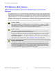
FCC Statement And Cautions FCC Statement And Cautions Federal Communications Commission Radio Frequency Interference Statement This equipment has been tested and found to comply with the limits for a Class A digital device pursuant to Part 15 of the FCC Rules. These limits are designed to provide reasonable protection against harmful interference when the equipment is operated in a commercial environment.
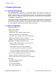
1. Product Overview 1. Product Overview 1.1. Functional Overview The RuggedBackbone™ RX1510 is a cost-efficient, rugged layer 3 switch and router. The RX1510’s modular and field replaceable platform allows you to select WAN, serial, and Ethernet options, making it ideally suited for electric power utilities, the industrial plant floor, and traffic control systems. The appliance’s compact form factor makes it ideal for pole mount applications or installation in restricted spaces.
1.
2. RuggedBackbone™ Modules 2. RuggedBackbone™ Modules The RX1510 chassis provides six module slots . Each slot accommodates a particular type of RuggedCom module. Figure 2.1, “RX1510 Chassis Slot Assignment” shows the module slots on the RX1510. Figure 2.1. RX1510 Chassis Slot Assignment The RX1510 chassis supports the following modules: LM1 through LM4 The RX1510 chassis supports up to four line module (LM) cards. For more information on line modules, see Section 2.2, “Line Modules (LM)”.
2. RuggedBackbone™ Modules 2.1. Front Panel The RX1510 Front Panel is equipped with an RS232 serial console port for initial management functions, and a locally connected 10/100Base-T Ethernet port for system management out of band from the switch fabric. Figure 2.2. Front View - RX1510 Other Front Panel features include: • Utility USB port. • Line module indicator LEDs. • Alarm Indicator LED, which indicates system alarm status. • Lamp Test / Alarm Cutoff (LT/ACO) button.
2. RuggedBackbone™ Modules 2.2. Line Modules (LM) The RuggedBackbone™ RX1510 supports four line modules in slots LM1 through LM4 . Several types of line modules may be ordered, depending on the type, speed, and number of Ethernet ports required. The following illustrations show the typical port configurations and connectors available for RX1510 line modules. For complete information on the available line modules, refer to the RuggedBackbone™ RX1510 data sheet. Only one T1/E1 module may be used per router.
2. RuggedBackbone™ Modules 2.2.3. SFP Modular Figure 2.12. FG5*: 2 × 1000LX/1000SX SFP Figure 2.13. FX5*: 4 × 100FX/100LX/100SX SFP Figure 2.14. 6FX50: 6 × 100FX SFP 2.2.4. WAN Figure 2.15. TC1: 1 × T1/E1 RJ45 Figure 2.16. E01: 1 × E1 BNC Figure 2.17. TC2: 2 × T1/E1 RJ45 Figure 2.18. E02: 2 × E1 BNC Figure 2.19. TC4: 4 × T1/E1 RJ45 2.2.5. Serial Figure 2.20. 6S01: 6 × Serial RJ45 2.2.6. Cellular Modem Figure 2.21. W11, W21, W32 Cellular Modem RuggedCom® RuggedBackbone™ Figure 2.22.
2. RuggedBackbone™ Modules 2.2.7. DDS - Digital Data Services Figure 2.23. D02: 1 × DDS RJ45 2.2.8. APE - Appplication Processing Engine Figure 2.24.
2. RuggedBackbone™ Modules 2.3. Power Supply The RX1510 may be equipped with one or two power modules. The use of two power modules is recommended to provide redundancy and load balancing. A single power module is capable of delivering a maximum of 42W, and accepts either AC or DC power at its input. Power modules may be ordered with a screw terminal block or with a pluggable terminal block.
3. Installation 3. Installation 3.1. Mounting The RuggedBackbone™ RX1510 features optional mounting brackets for panel and DIN rail mounting. The optional brackets attach to both sides of the appliance at the rear of the chassis. For panel mounting, the mounting bracket provides four mounting holes. For DIN rail mounting, the DIN adaptor mounts to a standard 1" DIN rail and is secured with a lock screw on each adaptor.
3. Installation Figure 3.3. DIN Rail Mounting: Side View 3.1.1. RX1510Dimensions Figure 3.4.
3. Installation Figure 3.5. RX1510Dimensions – Top View Figure 3.6.
3. Installation 3.2. Power Supply Wiring and Grounding The RX1510 supports dual redundant power supplies, power module 1 (PM1) and power module 2 (PM2). Power connections are located on the PM1 and PM2 module face plates. An optional chassis ground connection is located on the front panel as shown in . RX1510 products can be equipped with either a Phillips Screw Terminal Block or a Phoenix Plug Terminal Block.
3. Installation 3.2.3. Chassis Ground Connection The RX1510 chassis ground connection, shown in Figure 3.11, “Chassis Ground Connection”, uses a #10-32 screw. It is recommended to terminate the ground connection in a #10 ring lug. Torque on the chassis ground connection should not exceed 30 in-lbs (3.4 Nm). Figure 3.11. Chassis Ground Connection 3.2.4. AC Power Supply Wiring Figure 3.12.
3. Installation 3.2.5. DC Power Supply Wiring Examples + + Figure 3.13. Wiring for Two DC Power Supplies (24P or 48P modules shown) • For 125/230VAC rated equipment, a appropriately rated AC circuit breaker must be installed. • It is recommended to provide a separate circuit breaker for each power supply module. • Equipment must be installed according to applicable local wiring codes. 3.2.6. AC and DC Power Supply Wiring Example + Figure 3.14.
3. Installation • The placement of the AC and DC power supplies is not slot-dependent. Either PM slot can be used for AC or DC power. • For 110/230VAC rated equipment, an appropriately rated AC circuit breaker must be installed. • For 125/250VDC rated equipment, a appropriately rated DC circuit breaker must be installed. • For maximum redundancy in a dual power supply configuration, it is recommended to use two independent power sources.
3. Installation 3.4. Serial Console Port The serial console port on the front panel provides access to the boot-time control and configuration menu interface, and a console interface to the ROX™ operating system. The serial ports implement RS232 DCE on a RJ45 connector. Serial settings are: 57600 bps, 8 bits, No parity, 1 stop bit. See the illustration and table below for pin configuration and assignment. Figure 3.16.
3. Installation 3.6. WAN Ports: BNC The RX1510 supports optional E1 WAN ports with BNC connectors. The Tx and Rx connections are labelled on the line module. See the illustration below for the connection configuration. Rx Tx RTIP Chassis TTIP Chassis Figure 3.18. RJ45 T1/E1 Pin Configuration 3.7. Copper Ethernet Ports The RuggedBackbone™ RX1510 can be ordered with up to 10/100Base-TX ports that allow connection to standard CAT-5 UTP cable with RJ45 male connectors.
3. Installation Cabling Category 1000BaseTX Compliant Required Action <5 No New wiring infrastructure required. 5 Yes Verify TIA/EIA-568-A compliance. 5e Yes No action required. New installations should be designed with Category 5e or higher. 6 Yes No action required. >6 Yes Connector and wiring standards to be determined. Table 3.4.
3. Installation 3.8. Serial Ports: RJ45 The RX1510 supports serial port line modules with RJ45 connections. On power-up, all serial ports default to RS485 mode. Each port can be individually set to RS232, RS485, or RS422 mode via software. Pin RS232 Mode RS485 Mode RS422 Mode 1 RX- 2 Reserved 3 COM (Isolated GND) 4 COM (Isolated GND) 5 RX 6 TX 7 CTS 8 RTS Shield Figure 3.20. RJ45 Serial Pin Configuration RX+ TX/RX + TX + TX/RX - TX - Chassis GND Table 3.5.
3. Installation 3.10. DDS Rx and Tx LED Indications The DDS module features Rx and Tx LED indicators that display transmit and receive status. Figure 3.22. DDS Module Rx and Tx LED Indicators The following tables describe the DDS module Rx and Tx LED status indications: Rx LED Color GREEN YELLOW Status Frame sync detected and signal OK. Signal OK, but no frame sync. RED Loss of signal. OFF The interface is not enabled. Table 3.7.
3. Installation 3.11.1. Module Insertion – SFP Special attention must be paid to the orientation of SFP modules upon installation in the RX1510 chassis. The figure below shows the proper orientation of SFP modules installed in both upper and lower line modules. SFP modules on the upper row must be inserted top-side up. SFP modules on the lower row must be inserted top-side down. SFP modules should be inserted with the baillatch in the locked position. Figure 3.23. SFP module orientation Figure 3.24.
3. Installation Figure 3.25. SFP module removal 3.12. Fiber Ethernet Ports Depending on the order code of the product, the RuggedBackbone™ RX1510 can be equipped with several different types of fiber optic ports. The Transmit (TX) and Receive (RX) connections of each port must be properly connected and matched for proper link establishment and operation.
3. Installation 3.13. Cellular Modems The RX1510 can be equipped with cellular modem modules for operation on GSM, EDGE, HSPA +, or CDMA networks. The cellular modems feature 50 Ω SMA antenna connectors on the front plate of each module. The following cellular modem modules are available: Module Order Code Description W11 1 Port Cell Modem GSM,EDGE,HSPA+ W12 2 Port Cell Modem GSM,EDGE,HSPA+ W21 1 Port Cell Modem EVDO Rev.A Verizon Wireless W22 2 Port Cell Modem EVDO Rev.
3. Installation 3.13.1. GSM, EDGE, HSPA+ Cellular Modem Card The HSPA option is available for use on various GSM based networks. This option supports GSM, GPRS, EDGE, UMTS and WCDMA/HSDPA/HSUPA. The Main antenna and Receive Diversity antenna connections are made to the 50 Ω SMA connectors located on either side of the front faceplate. Supported frequency bands are given in the following table. For safe operation of the device, ensure that the maximum antenna gain is not exceeded.
3. Installation 3. Note the location of the SIM card cages. For modules W11 and W32, install the SIM card in SIM 1. For module W22, install a SIM card in both SIM 1 and SIM 2. 4. Top open a SIM card cage, slide the silver catch down towards the antenna connector end of the module and flip the cage open. 5. Hold the SIM card at its notched end, with its connectors facing down, and insert the SIM card into the cage. 6.
3. Installation 3.14. APE: Application Processing Engine 3.14.1. APE Overview The APE (Application Processing Engine) is an x86-based computer designed to occupy a single line module slot on the RX1510. The APE can host any x86-based operating system capable of running on a computer with similar specifications, and features a Gigabit Ethernet connection on the module faceplate. You can use the APE for a variety of functions, such as network monitoring, specialized applications, DNS applications, and more.
3. Installation 3.14.3. Secondary Network Interface In addition to the gigabit Ethernet interface on the faceplate, the APE features a gigabit Ethernet interface connecting to a port on the RX1510 chassis. The interface can be used by the operating system running on the APE as a normal network interface. The port can be configured from ROX™. Typical port parameters, such as speed, duplex, vlans, and more, can be configured.
3. Installation 3.14.4. Installing an Operating System We recommend that the operating system be installed and configured by users with experience in installing and administering the chosen operating system. To install an operating system on the APE, you need the following items: • DVI-D monitor. • Keyboard with USB connector. • Bootable USB flash drive or USB external CD/DVD drive with your operating system installation package.
3. Installation 3.14.5. The APE BIOS The APE module features a BIOS with functionality similar to that of a typical PC. You can configure the following BIOS settings: • System Time • Processor Options • Boot Options • Security Options For most purposes, these options are used sparingly unless there is a specific hardware or software requirement that requires a change. The most commonly changed options are the boot options, as the USB ports need to be made bootable to install an operating system.
3. Installation 3.14.8. FAQs Q: How do I use a CD or DVD to install an operating system on the APE module? A: Connect an external CD/DVD drive to one of the APE USB ports. If the external drive is powered through the USB port, ensure that it does not exceed the USB port power limitations (250 mA at 5 V), or use a drive that has an external power supply. Q: How do I install Windows from a USB flash drive? A: There are many articles on the Internet explaining how to do this.
4. Technical Specifications 4. Technical Specifications 4.1. Power Supply Specifications Input Range Power Supply Type Internal Fuse Rating Max.
4. Technical Specifications 4.4. Fiber Ethernet Port Specifications The following sections detail fiber optic specifications for ports that can be ordered with the modules on a RuggedBackbone™ RX1510. The user determines the type of optics at time of ordering, and can determine the modules installed on a particular unit by reading the factory data file via the ROX™ user interface. Section 4.4.1, “Fast Ethernet (100Mbps) Optical Specifications” and Section 4.4.
4. Technical Specifications 4.4.2. Gigabit Ethernet (1Gbps) Optical Specifications Fixed Gigabit Transceivers Connector Cable Tx λ (typ.) Type Type (µm) (nm) Order Code Mode FG01 MM LC 50/125 850 FG02 SM SC 9/125 FG03 SM LC 9/125 FG04 SM SC FG05 SM LC Rx Rx Distance Sensitivity Saturation (typ.) (dBm) (dBm) (km) Power Budget (dB) Tx min (dBm) Tx max (dBm) -9 -2.5 -20 0 0.5 1310 -10 -3 -20 -3 10 10 1310 -9.5 -3 -21 -3 10 11.
5. EMI And Environmental Type Tests 5. EMI And Environmental Type Tests Test IEC 61000-4-2 ESD IEC 61000-4-3 Radiated RFI IEC 61000-4-4 IEC 61000-4-5 IEC 61000-4-6 IEC 61000-4-8 IEC 61000-4-29 IEC 61000-4-11 IEC 61000-4-12 a Burst (Fast Transient) Surge Induced (Conducted) RFI Magnetic Field Severity Levels Enclosure Contact +/- 8 kV 4 Enclosure Air +/- 15 kV 4 Enclosure Ports 20 V/m Note a Signal ports +/- 4kV @ 2.5kHz Note a D.C. Power ports +/- 4kV 4 A.C.
5. EMI And Environmental Type Tests Test IEEE C37.90.3 ESD IEEE C37.90.2 Radiated RFI IEEE C37.90.1 IEEE C37.90.1 IEEE C37.90 IEEE C37.90 a Description Test Levels Enclosure Contact +/-2kV, +/-4kV, +/- 8kV Enclosure Air +/-4kV, +/-8kV, +/-15kV Enclosure ports 35 V/m Signal ports +/- 4kV @ 2.5kHz D.C. Power ports +/- 4kV A.C. Power ports +/- 4kV Earth ground ports +/- 4kV Fast Transient Oscillatory H.V. Impulse Dielectric Strength Signal ports 2.5kV common mode @1MHz D.C.
6. Agency Approvals 6. Agency Approvals Agency Standards TUV UL 60950-1:2007, CAN/CSA-C22.2 No. 60950-1-07 CE EN 60950, EN 61000-6-2 Comments CE Compliance is claimed via Declaration of Self Conformity Route FCC FCC Part 15, Class A CISPR EN55022, Class A FDA/CDRH 21 CFR Chapter 1, Subchapter J Laser Eye Safety ISO9001:2008 Designed and manufactured using an ISO9001: 2008 certified quality program ISO Table 6.1.
7. Warranty 7. Warranty RuggedCom warrants this product for a period of five (5) years from the date of purchase. This product contains no user-serviceable parts. Attempted service by unauthorized personnel shall render all warranties null and void. For warranty details, visit www.RuggedCom.com or contact your customer service representative. Should this product require service, contact the factory at: RuggedCom Inc.