
Network Router User Manual

2. RuggedBackbone™ Modules
RuggedCom® RuggedBackbone™ 12 RX1510 Installation Guide Rev 104
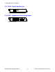
2.1. Front Panel
The RX1510 Front Panel is equipped with an RS232 serial console port for initial management
functions, and a locally connected 10/100Base-T Ethernet port for system management out of
band from the switch fabric.
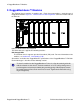
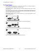
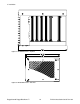
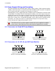
Figure 2.2. Front View - RX1510
Other Front Panel features include:
• Utility USB port.
• Line module indicator LEDs.
• Alarm Indicator LED, which indicates system alarm status.
• Lamp Test / Alarm Cutoff (LT/ACO) button.
• Removable 1GB Compact Flash (CF) card, which contains active and fallback installations of
the ROX™ operating system, along with the configuration database and other system data.
• Chassis ground connection.
For more information on connecting to the ports on the front panel, see the following topics:
• Serial Console: Section 3.4, “Serial Console Port”
• Management Ethernet Interface: Section 3.7, “Copper Ethernet Ports”
• Critical Alarm (Failsafe) Relay Interface: Section 3.3, “Critical Alarm Wiring”
2.1.1. Module Status LEDs
The front panel module status LEDs provide the following information:
LED Purpose Description
LM 1 through 4 Indicates the line module status.
Green = OK
Orange = Warning alert
Red = Configuration error
Table 2.1. Module Status LED Indications