
Network Router User Manual

3. Installation
RuggedCom® RuggedBackbone™ 23 RX1510 Installation Guide Rev 104
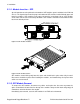
• The placement of the AC and DC power supplies is not slot-dependent. Either PM
slot can be used for AC or DC power.
• For 110/230VAC rated equipment, an appropriately rated AC circuit breaker must
be installed.
• For 125/250VDC rated equipment, a appropriately rated DC circuit breaker must be
installed.
• For maximum redundancy in a dual power supply configuration, it is recommended
to use two independent power sources.
• It is recommended to provide a separate circuit breaker for each power supply
module.
• Equipment must be installed according to applicable local wiring codes.
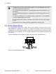
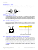
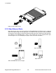
3.3. Critical Alarm Wiring
The Critical Alarm output relay signals critical error conditions that may occur on the
RuggedBackbone™ RX1510. The contacts are energized upon power-up of the unit and remain
energized unless a critical alarm condition is detected. Relay connections are shown in the Critical
Alarm Relay Connector diagram. You can configure control of the relay output through the ROX™
user interface.
A common application for this output is to signal an alarm in case of a power failure.
Figure 3.15. Critical Alarm Relay Connector