RuggedSwitch™ i800 Family Installation Guide www.ruggedcom.
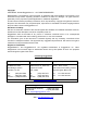
Copyright COPYRIGHT © 2008 RuggedCom Inc. ALL RIGHTS RESERVED Dissemination or reproduction of this document, or evaluation and communication of its contents, is not authorized except where expressly permitted. Violations are liable for damages. All rights reserved, particularly for the purposes of patent application or trademark registration. This document contains proprietary information, which is protected by copyright. All rights are reserved.
Federal Communications Commission Radio Frequency Interference Statement This equipment has been tested and found to comply with the limits for a Class A digital device pursuant to Part 15 of the FCC Rules. These limits are designed to provide reasonable protection against harmful interference when the equipment is operated in a commercial environment.
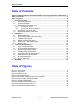
Table of Contents Table of Contents Federal Communications Commission Radio Frequency Interference Statement .. 3 Table of Contents............................................................................................................ 4 Table of Figures .............................................................................................................. 4 1 Product Overview.................................................................................................... 5 1.
Product Overview 1 Product Overview 1.1 Functional Overview The RuggedSwitch™ i800, or i-Series, is a family of compact, fully managed Ethernet switches designed to operate reliably in harsh industrial environments. The flexibility of the i800 family allows the user to choose from managed or unmanaged, regular or extended temperature, and a mix of fiber optic or copper interfaces, and fast or Gigabit Ethernet.
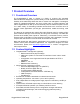
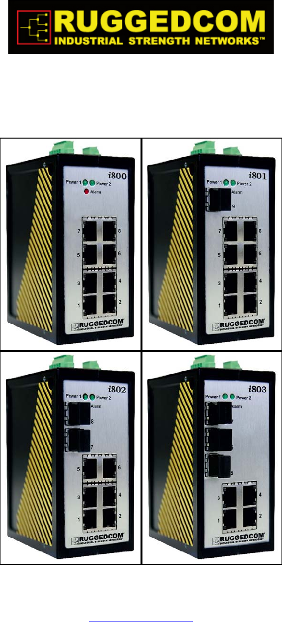
Product Overview 1.3 i800 Family Front Panel View Power Connector Fail-Safe Relay Power LEDs i802 Power 1 Power 2 Alarm LED Alarm Ports 5-7, 7&8, or 9: 10/100/1000Base Tx, 100FX, 1000SX/LX 8 Fiber port LEDs 7 Speed LEDs (top) 5 Ports 1 – 4/6/8: 10/100 BaseTx 6 Link/Act LEDs (bottom) 3 4 1 2 R RS-232 Console Port Memory Slot Figure 1: Front Panel The front panel shown is representative of the i800 family.
Product Overview 1.3.
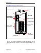
Product Overview 1.4 i800 Family Top Panel View DIN Rail mounting bracket back P1+ Power Connector P1- Fail-Safe Relay GND P2P2+ Chassis Ground Ratings: 12-24V , , 2A front Figure 2: Top Panel For details on connecting the power supplies and Ground, see Section 2.2. For details on connecting the Fail-Safe Relay, see Section 2.
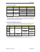
Product Overview 1.5 i800 Family Bottom Panel View Ports 5-7, 7&8, or 9: 10/100/1000Base Tx, 100FX, 1000SX/LX Ports 1 – 4/6/8: 10/100Base Tx front MEMORY SLOT Micro-SD Memory Slot RS-232 Console Port CONSOLE 57600-N-8-1 DIN Rail mounting bracket back Figure 3: Bottom Panel For details on connecting the console port, see Section 2.4. For a description of the memory slot, see Section 2.6.
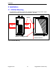
Installation 2 Installation 2.1 DIN Rail Mounting The i800 family of switches comes with a standard DIN rail mounting bracket. Figure 4 details the mounting configuration for a standard 1” DIN Rail.
Installation DC Input 1 front Ratings: 12-24V , P2+ P2- P1- P1+ back GND , 2A 2.2 Power Supply Wiring and Grounding DC Input 2 Chassis Ground Figure 5: DC Power supply and ground connections The low voltage DC power supply features reverse polarity protection and dual independent inputs, allowing the connection of two DC sources with the same nominal voltage to provide redundant power supplies. A list of power and ground connections follows in Table 3.
Installation Ratings: 12-24V , P2+ P2- P1- GND P1+ Ratings: 12-24V , P2+ P2- P1- P1+ GND , 2A , 2A Figure 6 illustrates the connections required for both single and dual power supply configurations: Figure 6: Power Supply Wiring Examples NOTES: • • • • Connect to the DC inputs according to the polarity markings on the unit. Chassis Ground must be connected to the protective earth. The internal connection between P1-.
Installation 2.3 Failsafe Output Wiring The Failsafe output relay is provided via a Phoenix connector to signal critical error conditions that may occur on the unit. The contacts are energized upon power up of the unit and remain energized until a critical alarm condition or power loss occurs. A common application for this output is to signal an alarm in the event of power failure.
Installation 2.4 RS232 Console Port Wiring The RS232 Console Port is used for initially configuring the unit. The connection is made using a DB9-Female to RJ45 console cable with the pin-outs listed in Table 5.
Installation 2.5 RJ45 Ports – Signal Description 10/100Base-TX ports allow connection to standard Category 5 (CAT-5) unshielded twisted-pair (UTP) cable with RJ45 male connectors. The RJ45 receptacles are directly connected to the chassis ground on the unit and can accept CAT-5 shielded twisted-pair (STP) cables. If shielded cables are used, care must be taken to ensure that a ground loop is not formed via the shield wire and the RJ45 receptacles at either end. Figure 9 shows the RJ45 port pin-out.
Installation 2.6 Memory Slot The i800 family of switches feature a removable microSD memory module to support the following features: • • • • Configuration update and backup Redundant firmware image Greatly expanded logging capability Fault-tolerant firmware update In case of unit failure, remove power from the unit and unplug any attached network, alarm, and console cabling.
Technical Specifications 3 Technical Specifications 3.1 Type Test Specifications IEC 61000-6-2 EMC: Generic Standards - Immunity for industrial environments Test Description Levels Enclosure Contact +/- 4kV Enclosure Air +/- 8kV 10 V/m, 80 to 1000Mhz IEC 61000-4-2 ESD IEC 61000-4-3 Radiated RFI Enclosure ports IEC 61000-4-4 Burst (Fast Transient) Signal ports +/- 1kV @ 5kHz DC Power ports +/- 1kV @ 5kHz Signal ports IEC 61000-4-5 Surge +/- 1kV line-to-earth/line +/- 0.
Technical Specifications 3.2 Environmental Specifications Parameter Range Ambient Operating Temperature -20 to 60°C -40 to 85°C (Optional) Ambient Storage Temperature Ambient Relative Humidity Vibration Shock Comments Ambient Temperature as measured from a 30 cm radius surrounding the center of the enclosure. -40 to 85°C up to 95% Non-condensing, 55°C, 6 cycles 1g 30g (10-500Hz) 11ms Table 9: Environmental Specifications 3.
Technical Specifications 3.5 RJ45 Ethernet Port Specifications Data Port Media Distance Connector Type 10/100 Mbps CAT-5 UTP or STP 100m RJ45 Table 13: RJ45 Ethernet Port Specifications 3.6 Fiber Optic Port Specifications Order Code Speed Standard Mode / Connector Tx (nm) Cable Type (um) _FG01 1000SX MM/LC 850 62.5/125 _FG03 1000LX SM/LC 1310 9/125 _FX11 100FX MM/LC 1310 62.
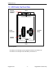
Technical Specifications 3.7 Physical Dimensions i802 Power 1 Power 2 Alarm 8 7 5.296 4.625 5 4.421 6 3.833 3 4 1 2 R 0.833 0.246 0.460 2.225 3.050 3.750 3.918 MEMORY SLOT 3.918 3.490 CONSOLE 57600-N-8-1 NOTE: All dimensions are in inches. Figure 10: Mechanical Specifications Parameter Dimensions Weight Enclosure Value 4.625 x 2.25 x 3.75 inches (117 x 57 x 95 mm) 1.5 lb (0.
Warranty 3.