
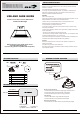
Installation Guide

3 4
1 2
Before returning to your retailer, please contact
support@runbisonlighting.com
if you have any questions or problem with this product
Item:
HT-US-ICCDR4-815/277-30113-C03-0-V1(30-50)
HT-US-ICCDR6-820/277-30113-C03-0-V1(30-50)
HT-US-ICCDR8-827/277-30112-C03-0-V1(30-50)
HT-US-ICCDR10-837/277-30111-C03-0-V1(30-50)
4 Inch/ 6 Inch/ 8 Inch/ 10 Inch LED Canless
Commercial Downlight
USE AND CARE GUIDE
SAFETY INSTRUCTION
PACKAGE CONTENT
Please read and understand all instructions before operate or install the product.
Failure to do so may lead to electric shock , fired or other injuries that could be be
hazardous or even fatal.
-Shut off the electricity to the wires that you are working on.
-Do not open,no user serviceable parts inside . Any changes or modifcations and
applications not expressly approved by the manufacturer could void the user’s
authority to operate the equipment and warranty.
WARNING
-Risk of fire or electric shock.
LED retrofit kit installation requires knowledge of luminaires electrical systems . Do not
attempt installation if not qualifed. Contact a qualifed electrician
-Install this kit only in the luminaires that have the construction features and
dimensions shown in the photographs and / or drawings.
-Do not exceed the input rating of theluminaire.
-Do not make or alter any open holes in an enclosure of wiring or electrical compo-
nents during kit installation.
-To prevent wiring damage or abrasion, do not expose wiring to edges of sheet metal
or other sharp objects.
- This device is not intended for use with emergency exits
- This luminaire has not been modified to operate LED Lamp . Do not attempt to install
or operate incandescent lamps or CFL in this luminaire.
-This retrofit kit is accepted as a component of a luminaire where the suitability of the
combination shall be determined by authorities having jurisdiction.
CAUTION
This device complies with Part 15 of the FCC rules. Operation is subject to the
following two conditions
1) this device may not cause harmful interference
2) this device must accept any interference received ,including interference that may
cause undesired operation.
Light
Cutting hole template
A
B
C
D
1
1
QTY
PARTS
Wire Nut
Wire Nut
3
2
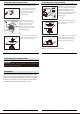
Electrical Connection Wiring:
1. Connect BLACK (line) driver lead to voltage supply Lineposition (HOT).
2. Connect driver WHITE lead to the NEUTRAL supplyposition.
3. Connect the GREEN ground lead to the supply groundlead.
0-10v Dimming:
4. Connect PURPLE lead to supply POSITIVE dimming lead
5. Connect PiNK lead to the supply NEGATIVE dimminglead.
NOT Using 0-10v Dimming:
6. Ensure PURPLE and PINK 0-10V dimming leads areproperly capped.
GENERAL WIRING DIAGRAM
GENERAL WIRING DIAGRAM
Purple Wire
120-277v
Black(Line)
White(Neutral)
Green(Grd)
Dimming wire
to 0-10v IEC
compliant control
Lead wire to
LED load
Purple(Dim+)
Pink(Dim-)
Blue(-)
Red(+)