OWNER ’S OPERATING MANUAL CW-43MC CW-50MC with Flat Panel Display Monitor
CONTENTS Introduction . . . . . . . . . . . . . . . . . . . . . . . . . . . . . . . . . . . . . . . . . . . . . . . . . . . . . . . . . . . 2 Features and Benefits . . . . . . . . . . . . . . . . . . . . . . . . . . . . . . . . . . . . . . . . . . . . . . . . . 2 High Altitude Operation . . . . . . . . . . . . . . . . . . . . . . . . . . . . . . . . . . . . . . . . . . . . . . . 2 Warnings and Safety Precautions . . . . . . . . . . . . . . . . . . . . . . . . . . . . . . . . . . . . . . . . . 3 Warning . .
INTRODUCTION Congratulations on your purchase of the CW-43MC/CW-50MC Plasma display! Your CW-43MC/CW-50MC will provide you with many years of enjoyment no other plasma can match. It is compatible with current NTSC and PAL systems, as well as DTV standards. And since the display is the 16:9 aspect ratio, DVD widescreen movies and Digital Television will look the way they were meant to look- in the widescreen format.
WARNINGS AND SAFETY PRECAUTIONS CAUTION: To turn off main power, be sure to remove the plugs from power outlets. The power outlet socket should be installed as near to the equipment as possible, and should be easily accessible. REMARQUE: Pour mettre l’appareil hors circut, s’assurer de retirer la fiche de la prise d’alimentation. La prise d’alimentation doit être installé aussi proche que possible de l’appareil et doit être facile d’ accès.
WARNING This equipment has been tested and found to comply with the limits for a Class ‘B’ digital device, pursuant to Part 15 of the FCC Rules. These limits are designed to provide reasonable protection against harmful interference when the equipment is operated in a commercial environment. This equipment generates, uses, and can radiate radio frequency energy and, if not installed and used in accordance with the Installation Manual, may cause harmful interference to radio communications.
LIMITED WARRANTY Congratulations on your purchase of a Runco International video product and welcome to the Runco family! We believe Runco produces “The World’s Finest Home Theater Products”. With proper installation, setup and care, you should enjoy many years of unparalleled video performance. This is a LIMITED WARRANTY as defined in the Magnuson-Moss Warranty Act. Please read it carefully and retain it with your other important documents.
This Limited Warranty only covers failure due to defects in materials and workmanship that occur during normal use and does not cover normal maintenance.
OPERATION General Overview The Runco CW-43MC and CW-50MC are standalone flat panel plasma displays with outboard VivixII™ video processing. With 1024 x 768 native resolution for the CW-43MC and 1280 x 768 native resolution for the CW-50MC, both are capable of imaging native HDTV. The CW-43MC and CW-50MC include a DVI digital input as well as standard analog inputs. QUICK SETUP Instructions 1. Install the Plasma display. This could be either table mount or wall mount configurations. 2.
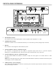
INPUTS AND CONTROLS ��� ����� �� ����� ������� �� ��� ������� � ��� �� �� �� �������� � ���������� �� ������ � ������� � � � ��� ������������� ����� �������������������� ������� � ����������� �� �������������������� � �������������� ����� ����� ������������ ����� ������ ����� ������ ����� � � ������� �������������������������������������������������������������������� ���������� 1 SPEAKER (R) terminal For connection of an external right speaker.
7 DIGITAL RGB (INPUT2) (DVI-D jack-non HDCP) Use to connect a computer resolution only. (VESA standard) 8 AUDIO (INPUT2) (Stereo mini jack) Used to obtain sound when INPUT1, INPUT2 is selected. Connect this jack to the audio output connector of the device connected to the plasma display’s INPUT1 or INPUT2.
CONNECTING THE PLASMA DISPLAY Modular Controller Card - Input Connections Plasma Rear View DVI Component S-Video Composite Push Button INPUT 5 DVI SOURCE INPUT (WITH HDCP DECRYPTION): (Digital 480P, 720P, 1080i): Input for set top box or PC with DVI digital output. INPUT 4 COMPONENT INPUT: Component video is the best type of signal that can be used. The most common sources that use component outputs are DVD players, and it is highly recommended that component be used when possible.
FRONT PANEL 12 3 4 1. STANDBY Indicator This indicator is red during standby mode. The flashing pattern is also used to indicate error messages. 2. ON Indicator Lights green when the plasma display is operating. When flashing, the indicator is used to indicate error messages. The indicator flashes green once every one second when the (AUTO POWER OFF) function is operating. 3. Display Stand Optional accessory for tabletop mount. 4.
REMOTE CONTROL DESCRIPTION Plasma Remote Control A. ASPECT RATIO Press to change the aspect ratio or geometry of the image. Different resolutions will allow for different aspect ratios. B A B. RGB SETUP When entering a computer-type (VESA) signal, press this to automatically center and resize the image. D G C. POWER Press this to cycle the monitor between on and standby. ASPECT RATIO POWER RGB SETUP C PC/HDTV-1 HDTV-2 1 2 SDTV-1 SDTV-2 3 4 INFO F DIGITAL IN I H T (svc)* MENU D.
MENUS for VIDEO NTSC, PAL or DIGITAL 480P and HDTV OSD Menus for Video NTSC, PAL or Digital 480p & HDTV These menus will appear only when displayed for video. CINEMAWALL INPUT 3 SCREEN PICTURE CONTRAST BRIGHTNESS COLOR TINT SHARPNESS : : : : : SET UP OPTION 0 0 0 0 0 1. PICTURE Tab The PICTURE menu allows for adjustment of picture that are unique per input and stored automatically. • CONTRAST is used to set the white level. • BRIGHTNESS. is used to set the black level.
MENUS for VIDEO NTSC, PAL or DIGITAL 480P and HDTV OSD Menus for Video NTSC, PAL or Digital 480p & HDTV This menu will appear only when displayed for video. CINEMAWALL PICTURE SCREEN INPUT 3 SET UP LANGUAGE ENERGY MODE PDP PROTECT ORBITER SIDEBAR ADJ. AUTO SET UP MODE INPUT PRIORITY AUDIO OUT LEVEL : : : : : : : : OPTION ENGLISH AUTO OFF OFF OFF OFF OFF FIXED 4.
MENUS for PC/HDTV-I D-SUB INPUT OSD Menus for PC/HDTV-I D-Sub Input These menus will appear only when displayed for computer. CINEMAWALL PICTURE INPUT 1 SCREEN CONTRAST BRIGHTNESS R. ADJUST G. ADJUST B. ADJUST H. SHARPEN V. SHARPEN : : : : : : : SET UP OPTION 0 0 0 0 0 0 0 • CONTRAST is used to set the white level. • BRIGHTNESS is used to set the black level. • R., G., B. ADJUST can be adjusted to set color balance. • H. and V.
INSTALLER MENUS for VIDEO NTSC, PAL or DIGITAL 480P and HDTV INSTALLER ADJUST Menus for Video NTSC, PAL or Digital 480p & HDTV These menus will appear only when displayed for video. Gaining access to the INSTALLER ADJUST Menu is done by pressing the installer adjust button below SDTV-2 button (number 4) using a small paperclip (with no menu present). Press menu at any time to exit INSTALLER ADJUST mode. The adjustments are stored automatically. (see page 12) INPUT 3 INSTALLER ADJUST PICTURE 1.
INSTALLER MENUS for VIDEO NTSC, PAL or ATSC INSTALLER ADJUST Menus for Video NTSC, PAL or ATSC These menus will appear only when displayed for video. 4. SETUP Tab • GAMMA is the relationship between pixel value and displayed intensity. • BRT. ENHANCE is used to enhance the black levels. • SUB VOLUME is used to configure sub-woofer levels. 5. OPTION Tab • PDP PROTECTION allows for automatic switching of the displayed image at regular intervals.
ASPECT RATIOS There are four aspect ratios available that can be selected for video signal inputs. 16:9 Screens: • ANAMORPHIC: The image is compressed vertically, but anamorphic software will appear properly proportioned. This is best suited for use with 16:9 DVD’s. ����������������� • STANDARD 4 x 3: The input signal will be scaled to fit in the center of the 16:9 sceen.
RS-232C ADJUSTMENT MODE Through the unit’s RS-232 terminal, it is possible to use the PC to make various adjustments and settings. 1) About the RS-232C Adjustment Mode • Adjustments in the RS-232C adjustment mode: - The adjustments are written to the same memory area as for the installer mode. 2) Display screen in the RS-232C adjustment mode: • The screen shown below illustrates the set ID number is displayed in the ‘--’ area at the upper left part of the screen.
RS-232C ADJUSTMENT MODE Interface 1) Connector: D-sub 9 pins (male) 2) Pin Layout: Pin No. Signal 1 NC (not connected) 2 TxD (Transmit Data) 3 RxD (Receive Data) 4 NC (not connected) 5 GnD 6 NC (not connected) 7 NC (not connected) 8 RTS (Request to Send) 9 NC (not connected) 1 5 6 9 3) Baud Rate: 9600 bps (standard) (switchable to 1200, 2400, 4800, 19200, 38400 bps) NOTE: The baud rate of this display should be set to match the baud rate of the computer.
RS-232C ADJUSTMENT MODE Interface 6) Protocol: From computer to plasmas display: (1) When sending one command at a time: STX (02 hex) ID (2 Byte) COMMAND (3 Byte or 6 Byte) ETX (03 hex) (2) When transmitting commands in batches (up to max.
RS-232C Commands How to read this table: • RS-232C Adjustment Validity: Indicates whether or not the RS-232 adjustment mode can be used. • Normal Validity: Indicates whether or not the normal-operation mode can be used • Numerical Direct Validity: When a number (3-digit number) is attached to the end of a command, the command can directly set that adjustment value.
Command Name C D E F Full Name RS-232C Adjustment Validity Normal Validity Description Numerical Direct Validity CTP COLOR TEMP: ******** ● Displays the current COLOR TEMP. CTPS01 COLOR TEMP.: 1 ○ Sets the COLOR TEMP. to LOW (equal to -3000K) CTPS02 COLOR TEMP.: 2 ○ Sets the COLOR TEMP. to MID-LOW (equal to -2000K) CTPS03 COLOR TEMP.: 3 ○ Sets the COLOR TEMP. to MIDDLE (±OK, standard) CTPS04 COLOR TEMP.: 4 ○ Sets the COLOR TEMP. to MID-HIGH (equal to +1000k) CTPS05 COLOR TEMP.
Command Name F G H I Full Name RS-232C Adjustment Validity Normal Validity Description Numerical Direct Validity FMK SCREEN MASK: ##### ● Displays the current SCREEN MASK setting. FMKS00 SCREEN MASK: OFF ○ Sets the SCREEN MASK to OFF. FMKS02 SCREEN MASK: INVERSE ○ Sets the SCREEN MASK to INVERSE (negative-positive inversion) FMKS03 SCREEN MASK: WHITE ○ Turns ON the WHITE mask. FMKS04 SCREEN MASK: RED ○ Turns ON the RED mask.
Command Name L M O Full Name RS-232C Adjustment Validity Normal Validity Function Numerical Direct Validity LEN FRONT INDICATOR: OFF ○ LEY FRONT INDICATOR: ON ○ LNN LOUDNESS: OFF ○ ○ Disables LOUDNESS. LNY LOUDNESS: ON ○ ○ Enables LOUDNESS. MCD COLOR DECODING: ****** ● Displays the current COLOR DECODING MCDS01 COLOR DECODING: RGB ○ Sets COLOR DECODING to RGB (VIDEO). MCDS02 COLOR DECODING: COMPONENT1 ○ Sets COLOR DECODING to COMPONENT1 (Y CbCr).
Command Name P R S T Full Name RS-232C Adjustment Validity Normal Validity Function Numerical Direct Validity PLN BRT. ENHANCE: OFF ○ PLY BRT. ENHANCE: ON ○ POF - ○ PON - PUC CINEMAMODE: ###### ● Displays the current CINEMAMODE setting. PUCS00 CINEMAMODE: OFF ○ Turns CINEMAMODE OFF. PUCS01 CINEMAMODE: STANDARD ○ Sets CINEMAMODE to STANDARD. PUCS02 CINEMAMODE: ADVANCE ○ RHI R. GAIN: *** ○ ○ Adjusts R. HIGH. RLW R. OFFSET: *** ○ ○ Adjusts R. LOW.
Command Name U V Full Name RS-232C Adjustment Validity Normal Validity Function Numerical Direct Validity UPO # ○ ○ Adds 10 to the adjustment value. UPn # ○ ○ Adds n to the adjustment value (n = 1 to 9). UPF # ○ ○ Sets the adjustment value to maximum. USC UNDERSCAN: *** ○ Displays the current UNDERSCAN setting. USCS00 UNDERSCAN: OFF ○ Turns the UNDERSCAN setting OFF. USCS01 UNDERSCAN: ON ○ Turns the UNDERSCAN setting ON. VOL VOLUME: *** ○ VPS V.
GET Commands What are GET Commands? • They are commands for outputting TXD such as adjustment data from the internal microcomputer of the plasma display to a PC. • Adjustment data, etc., is output in ASCII code. NOTE: Command names are given inside brackets < >. • Data output format STX (o2hex) Data Data .... Checksum ETX (03hex) NOTE: 1) GET commands will be invalid when no ID NO. Set is assigned to the set. 2) GET commands will be invalid when wildcard (*) is used in the ID No.
2) (GET PICTURE DATA: Gets installer/Picture data.) Order Data Contents Size Remarks 1 CONTRAST 3byte # 2 BRIGHTNESS 3byte # 3 C. DETAIL R (RED) 3byte # 4 C. DETAIL Y (YELLOW) 3byte # 5 C. DETAIL G (GREEN) 3byte # 6 C. DETAIL C (CYAN) 3byte # 7 C. DETAIL B (BLUE) 3byte # 8 C. DETAIL M (MAGENTA) 3byte # 9 H SHARPEN 3byte Outputs dummy data for video signal. # 10 V SHARPEN 3byte Outputs dummy data for video signal.
5) (GET STATUS SETUP: Gets menu and installer SETUP data.) Order Data Size Output Remarks 1 GAMMA 1byte 1: GAMMA 2.0 3: GAMMA 2.2 5: DRE HIGH 7: HIGH CNT. 2 BRT. ENHANCE 1byte 0:OFF 3 SUB VOLUME 2byte 00 to 20 4 COLOR TEMP.
6) (GET STATUS OPTION: Gets menu and installer OPTION data.) Order Data Size 1 ENERGY MODE 1byte 1: STANDARD 3: MODE 2 5: AUTO 2 ORBITER 1byte 0:OFF 1: ON 3 MASK CONTROL 1byte 0:OFF 1: ON 4 AUDIO OUT 1byte 1:FIXED 2: VARIABLE 5 SCREEN MASK 1byte 0: OFF 2: INVERSE 4: RED 6: BLUE 6 SIDEBAR ADJ. 1byte 1: NORMAL 2: OVERLAY1 3: OVERLAY2 7 R. SIDEBAR ADJ. LEVEL 3byte 000 to 255 8 G. SIDEBAR ADJ. LEVEL 3byte 000 to 255 9 B. SIDEBAR ADJ.
DIMENSIONS CW-43MC Plasma � ����� ����� ������ ������ ������ ������ ��������� ������ ������ ����� ������ ������ � 32 ������ ������ ����� ������ ����� � ������
CW-50MC Plasma � ����� ����� ������ ������ ������ ������ ������ ��������� ������ ������ ������ ����� 33 ������ ����� ����� ������ � ������ ������ �
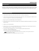
SPECIFICATIONS Plasma CW-43MC Native Resolution: Screen Size: Screen Aspect Ratio: Available Aspect Ratios: 1024 x 768 43 in. (diagonal) 16:9 4:3, Letterbox, 16:9 Anamorphic, VirtualWide Image Area (W x H): 37 3/8 in. (949.30 mm) x 21 1/8 in. (536.
RUMA-011000 11-08-04 v2.1 Runco International • Union City, CA 94587 • Ph: 510-324-7777 • Fax: 510-324-9300 • www.runco.