OWNER'S OPERATING MANUAL THE WORLD'S FINEST HOME THEATER PRODUCTS RUNCO Super HDTV D T V V i d e o P r o j e c t o r DTV-1101 DTV Capable CRT Projector
Table of Contents Table of contents .................................................................................................................................................................................. i Runco Limited Warranty ..................................................................................................................................................................... ii Safety Instructions ...................................................................................
Table of Contents Service Mode ..................................................................................................................................................................................... 7-1 Starting up the Service mode .................................................................................................................................................... 7-1 Overview flowchart 'Service' mode ...............................................................................
Runco Limited Warranty Congratulations on your purchase of a Runco video product and welcome to the Runco family! We believe Runco produces the world’s finest home theater products. With proper installation, setup, and care, you should enjoy many years of unparalleled video performance. Please read this consumer protection plan carefully and retain it with your other important documents. This is a “LIMITED WARRANTY” as defined by the U.S.
Safety Instructions 1 SAFETY INSTRUCTIONS Notice on Safety This equipment is built in accordance with the requirements of the international safety standards EN60950, UL 1950 and CSA C22.2 No.950, which are the safety standards of information technology equipment including electrical business equipment.
Safety Instructions WARNING FOR THE CUSTOMERS: THIS APPARATUS MUST BE GROUNDED (EARTHED) via the supplied 3 conductor AC power cable. (If the supplied power cable is not the correct one, consult your dealer.) Refer all servicing to qualified service personnel. A. Mains lead (Power cord) with CEE 7 plug: A. B. C. D. The wires of the mains lead are colored in accordance with the following code. Green and yellow: earth (safety earth) Blue: neutral Brown: line (live) B. Power cord with ANSI 73.
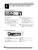
Location and Function of Controls 2 LOCATION AND FUNCTION OF CONTROLS REAR PANEL TERMINOLOGY PORT 4/5 (RGB + HV) Comp/H sync V sync PORT 6 REMOTE COMMUNICATION PORT 3 . . . . . R 1 1 2 3 2 G B 4 3 Communication Port * Not used. 5 4 - unlit: mains (power) switch is not pressed. - lit: mains (power) switch is pressed and the indicated color shows the projector mode: Green: operational mode of the projector. Red: standby mode of the projector.
Location and Function of Controls Control Panel Terminology a. The Local Keypad (built in RCU) Gaining Access The local keypad is built in into the rear of the projector. Push once on the door cover and it will open. It is possible to turn it 90°. This local keyboard has the same functions as the Remote Control Unit (RCU). PORT 4/5 (RGB + HV) Comp/H sync V sync PORT 6 REMOTE . . . . . PORT 3 COMMUNICATION R B G b.
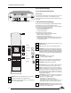
Connections 3 CONNECTIONS AC Power (mains) Cord Connection Use the supplied power cord to connect your projector to the wall outlet. Plug the female power connector into the male connector at the front side of the projector. V NOM 1 MAX FREQ 120/230 Volt 7/5 Amp 50/60Hz RS232 IN RS232 OUT IR REMOTE Power Check Power voltage indication is on the sticker on the rear side of the projector. The power voltage is indicated by the serial number sticker.
Connections Start Up with Full White Image. If no action is taken, a white image will be displayed for 20 minutes. This white image will be shifted on the faceplate of the CRT to avoid a CRT burn in. During this warm-up period, it is possible to interrupt this white image projection by pressing the EXIT key. If EXIT is pressed, the remaining warm-up period will be skipped. During the warm-up period, every 30 seconds a text box with the remaining time will be displayed on the screen for 2 seconds.
Connections Connecting a RGB Analog Source to Port 3 Connect your RGB source via an interface to Port 3. Always use an interface when a computer and local monitor have to be connected to the projector. PORT 4/5 (RGB + HV) PROJECTOR MODE Comp/H sync V sync Pin configuration D9 connector of the Analog input: 1 not connected 2 ground RGBS 3 RED 4 GREEN 5 BLUE 6 ground RGBS 7 ground RGBS 8 Hor/comp. sync 9 Vert. sync PORT 6 REMOTE COMMUNICATION . . . . . PORT 3 R ON OFF B G ANALOG INTERF. 120MHz .
Connections Connecting a Component Video Source to Port 4/5 PORT 4/5 (RGB + HV) Comp/H sync V sync PORT 6 REMOTE COMMUNICATION PORT 3 . . . . . R A component video source can be connected to the projector via the Port 4/5. The projector detects automatically where the sync signal is located. To select the component video input, select component from the source selection menu.
Controlling 4 CONTROLLING Caution: Do not display a stationary image with full brightness and contrast for longer than 20 minutes, otherwise you risk damage to the CRTs. Battery Installation in the RCU A new battery has been packaged inside the plastic bag with the power cord. Before using the RCU, install the battery first. Remove the battery cover on the backside of the RCU by pushing the indicated handle a little to the bottom of the RCU. Lift the top side of the cover at the same time (fig. 1).
Controlling Projector Address The Runco DTV-1101 can be controlled with a. the RCU b. the built-in RCU (local keypad) a. Software set up of the projector address The procedure and results of controlling the projector with either of these RCU options is essentially the same. See 'Change Projector Address' in Chapter 2, 'Service Mode'. Every projector requires an individual address between 0 and 255, which is set in the Service mode.
Controlling How to Display a Projector Address Analog Picture Controls Press the ADDRESS key (recessed key on the RCU) with a pencil. The projector's address will be displayed in a 'text box'. This text box will disappear after a few seconds. The analog picture controls can be adjusted with the RCU. The control keys are located on the lower right side of the key panel of the RCU and indicated with the name of the control and an icon.
Controlling Controlling Chained Projectors Projectors can be controlled individually as well as in a group. For individual control, see previous pages. For group control of the projectors, see Input Selection and Analog Picture Control. Program the 'zero address' into any RCU. Press on the address key and key in the address ('0') with the numeric keys on the RCU itself. Once address '0' is pressed, all projectors will be controlled together until a new address is entered on the RCU.
Start Up of the Adjustment Mode 5 START UP OF THE ADJUSTMENT MODE Adjustment Mode All picture geometry and convergence adjustments are made while in the 'Adjustment Mode'. Press the ADJUST key to enter the 'Adjustment Mode'. Enter the digits with the numeric keys on the RCU. You are now in the 'Adjustment mode'. The Control disk is used to make menu selections and also vertical and horizontal adjustments. The ENTER and EXIT keys are used to move forward and backward through the menu structure.
Random Access Adjustment Mode 6 RANDOM ACCESS ADJUSTMENT MODE ADJUSTMENT MODE Select a path from below : Starting Up the Random Access Adjustment Mode SOURCE SELECTION ADJUSTMENT MODE EYE Q Push the control disk up or down to highlight "RANDOM ACCESS" and then press ENTER. Some items in the Random Access Mode are password protected (when the password function is enabled). Enter your password to continue. All other password protected items are now also available if you stay in the Adjustment Mode.
Random Access Adjustment Mode From previous page From previous page H SIZE V LINEARITY V SIZE TOP BOTTOM BLANKING LEFT RIGHT GREEN ONLY RANDOM ACCESS ADJUSTMENT MODE CONVERGENCE RED ON GREEN BLUE ON GREEN RED SETUP PATTERN SELECTION FOCUSING GREEN BLUE RED GREEN BLUE COLOR SELECT RED AND GREEN BLUE AND GREEN RED AND BLUE 6-2
Random Access Adjustment Mode Selecting Setup Pattern If an external source is connected to the projector, this menu will be displayed. Push the control disk up or down to highlight the desired setup pattern and then press ENTER. Genlocked pattern: internally generated crosshatch pattern, based on the scan rate of the external source.
Random Access Adjustment Mode Random Access Adjustment Mode Selection Menu This is the main menu for the Random Access Adjustment Mode.
Random Access Adjustment Mode Sync Fast/Slow Adjustment The sync function is used to minimize horizontal jittering or tearing at the top to the displayed image. Highlight SYNC by pushing the control disk up or down and press ENTER to toggle between FAST and SLOW. Note: SYNC is normally used in the SLOW position.
Random Access Adjustment Mode Color Select Highlight COLOR SELECT by pushing the control disk up or down and press ENTER to display the Color Select Menu. ENTER continues to the Color Select Menu EXIT will return to Internal Crosshatch Selection or Setup Pattern Selection Menu ADJUST returns to Operational Mode Use the control disk to highlight a color (CRT) or combination of colors to display the projected image in that specific color. To select a new color, press ENTER.
Random Access Adjustment Mode Focusing Before starting the focusing adjustment, be sure the lenses are correctly focused. Push the control disk up or down to select FOCUSING and press ENTER. RANDOM ACCESS ADJUSTMENT MODE PICTURE TUNING GEOMETRY CONVERGENCE FOCUSING COLOR SELECT ENTER continues to the Focusing (Color Select) Menu. EXIT returns to Internal Crosshatch Selection or Setup Pattern Selection Menu. Select with or then to return. FOCUSING ADJUST returns to Operational Mode.
Random Access Adjustment Mode Geometry Adjustments The geometry adjustments have to be done only on the green image. These adjustments are automatically implemented for the other color images: Left-right (EW) and Top-Bottom Corrections, Blanking, Horizontal Amplitude, Vertical Amplitude, Vertical Linearity, and Horizontal Phase.
Random Access Adjustment Mode Raster Shift Adjustment The green raster must be centered both horizontally and vertically on the center of the CRT surface. To center the green raster, look into the green lens and use the control disk to move the raster. CAUTION: It is necessary to look into the lenses to perform these adjustments. To avoid eye discomfort while looking into the lenses, reduce the contrast and gradually increase the brightness level until the raster becomes visible on the face of the CRT.
Random Access Adjustment Mode Left-Right (East-West) Adjustments Left-right adjustments affect only the vertical lines of the projected image. Only the green image is displayed while making left-right adjustments. The red and blue images will automatically be corrected in the same manner. Convergence corrections are automatically disabled for the duration of these adjustments.
Random Access Adjustment Mode Seagull Correction Use this correction only if, after adjusting the vertical lines with the side bow or side keystone, an 'S' deformation is still visible on the left and the right side of the image. The default value on the bar scale for this correction is 50. Push the control disk up or down to highlight SEAGULL CORRECTION on the Left-Right Menu and then press ENTER.
Random Access Adjustment Mode Top-Bottom (North-South) Adjustments Top-Bottom and center adjustments affect only the horizontal lines of the projected image. To start up the Top-Bottom and center corrections, follow the next procedure: Push the control disc up or down to highlight TOP-BOTTOM (N/S) on the Geometry Menu and then press ENTER. Only the green image is displayed while making top-botton adjustments. The red and blue images will automatically be corrected in the same manner.
Random Access Adjustment Mode Seagull Correction Use this correction after the image has been adjusted with top and bottom bow and keystone. If a deformation is still visible (like a seagull) on top and bottom of the image, proceed to the seagull correction. Due to interaction, it is possible that the top and bottom bow will have to be readjusted after adjusting the seagull correction to obtain an improved image. The default value on the bar scale of this correction is 50.
Random Access Adjustment Mode Vertical Linearity Adjustment The vertical linearity adjustment function corrects for vertical nonlinearities that extend from the center of the image to the top and bottom of the image. Push the control disk up or down to highlight V LINEARITY on the Geometry Menu and then press ENTER.
Random Access Adjustment Mode Blanking Adjustments Blanking adjustments affect only the edges of the projected image and are used to frame the projected image on to the screen and to hide or black out unwanted information (or noise). A 0% on the bar scale indicates no blanking.
Random Access Adjustment Mode Convergence Adjustment Convergence adjustments affect both the horizontal and vertical lines of the setup pattern. These adjustments are performed on the red image while superimposed on the green image and then on the blue image while superimposed on the green image. Start with the Coarse Convergence Adjustments and finalise with the Fine Convergence Adjustments.
Random Access Adjustment Mode Vertical Corners To make a coarse adjustment of the red or blue horizontal lines in zone 10, 14, 18, and 22 simultaneously, highlight 'Vertical Corners' and press ENTER to start the adjustment. Select with or then to return. COARSE CONVERGENCE HORIZONTAL SIDES VERTICAL CORNERS Select with or then to return Hint : - Adjust until the red or the blue horizontal lines are on the green lines or as close as possible to the green lines.
Service Mode 7 SERVICE MODE Starting up the Service Mode Use the control disk to highlight 'Service' and then press ENTER. ADJUSTMENT MODE Some items in the Service Mode are password protected (when the password function is active). Enter your password to continue. All other password protected items will now also be available if you stay in the Adjustment Mode. ENTER continues to the Service Mode Main Menu. EXIT returns to the Operational Mode. The service items are combined in two service menus.
Service Mode Identification Highlight 'Identification' with the control disk and press ENTER. SERVICE MODE IDENTIFICATION COPY A BLOCK DELETE A BLOCK DELETE ALL BLOCKS CHANGE PASSWORD CHANGE LANGUAGE RUN TIME SET TO MIDPOSITION CONVERGENCE MID DYNAMIC ASTIGMATISM The 'Identification' screen gives information concerning: - projector address, to change the address of your projector, contact a qualified service technician. - software version MORE... Select with or then to return.
Service Mode Deletion of Blocks This item is password protected. The delete function is used to clear all data (settings) from an adjustment block. A delete can be given: - block by block or - for all blocks Deleting Block by Block The delete a block function deletes the settings of a selected block. Highlight 'Delete A Block' with the control disk and press ENTER.
Service Mode Change Password This item is password protected. Highlight 'Change Password' with the control disk and press ENTER. The current password is displayed. The new password must consist of 4 digits between 0 and 9. Push the control disk to the left or to the right to select the digits to be changed. Use the numeric keys to enter the new digits. Press ENTER to save the new password. Before saving the new password, a confirmation screen will be displayed.
Service Mode Set to Midposition This item is password protected. Highlight 'Set to Midposition' with the control disk and press ENTER to set all settings to their midposition. A confirmation menu will be displayed first. SERVICE MODE IDENTIFICATION COPY A BLOCK DELETE A BLOCK DELETE ALL BLOCKS CHANGE PASSWORD CHANGE LANGUAGE RUN TIME SET TO MIDPOSITION CONVERGENCE MID DYNAMIC ASTIGMATISM MORE... ENTER will set all settings to their midposition.
Service Mode Dynamic Astigmatism (Spot Shape Adjustment) The spot shape adjustments correct the spot shape in 8 different areas on the screen and for the three colors separately. The spot shape is adjusted according to the axial axises and the diagonal axises when using the arrow keys on the RCU. These adjustments have to be done on a dot pattern (e.g. the internally generated pattern) with standard line frequency (15 kHz).
Service Mode G2 Adjust This item is password protected. Highlight 'G2 Adjust' with the control disk and press ENTER to continue. A safety notice will be displayed on the screen since it is necessary to open the top cover to adjust the G2. SERVICE MODE G2 ADJUSTMENT GAMMA CORRECTIONS CRT RUN IN CYCLE PROJECTOR WARM UP CRT DRIVE MODE MORE... G2 adjustment should be performed by Runco personnel or Runco authorized dealers. If you are qualified, press ENTER to continue.
Service Mode Projector Warm-Up Highlight 'Projector Warm-Up' by pushing the control disk up or down and press ENTER to select the Projector Warm-Up Menu. The ON/OFF option can be toggled with the ENTER key. When in the ON position (and the CRT Run in Cycle is OFF), the projector can start up with a warm-up period of 20 minutes. During the start up a warm-up menu will displayed.
Service Mode Memory Banks This function allows the creation of various aspect ratios while the horizontal scan rate stays the same. If this feature is ON, then the unit will have the capability of having eight (8) separate aspect ratios within the same frequency (there are a total of 32 separate memories if all eight memory banks are used. For example, then a total of 4 frequencies can be input [4 freqs x 8 memory banks = 32]).
Messages, warnings and failures 8 INPUT 05 Fh= 31.5 kHz Fv= 60 Hz SOURCE 05 enter password xxxx MESSAGES, WARNINGS AND FAILURES When selecting a new source, information about this source will be displayed on the screen. Source number, horizontal, and vertical frequencies of the displayed source. Announcement of the selected source. Message to enter your password. Password contains 4 digits. source not available WARNING : invalid key entry WARNING : End of adjustment range.
Specifications 9 SPECIFICATIONS Scan Frequency: Horizontal: 15-75 kHz autolock Vertical: 37-155 Hz Safety Regulations: Complies with: UL, FCC Class B, CE, C-Tick Retrace Time: Horizontal: 2.5 mS Vertical: 200 mS Environment: 32-104o F (0-40o C) Humidity: 0-90% non-condensing Bandwidth: 120 MHz (-3 dB) Storage: 10-122o F (-12-50o C) CRT: 9-inch, high brightness, high definition liquid coupled tubes with electromagnetic focus Lenses: Optical Resolution: Cabinet Dimensions: Width: 31 in.
RUMA-003800 rev 10-00 2463 Tripaldi Way Hayward, CA 94545 510-293-9154 Fax: 510-293-0201