O W N E R ’S O P E R A T I N G M A N U A L TM XP-50DHD / XP-50DHDxa XP-65DHD / XP-65DHDxa XP-103DHD High Definition, 1080p Flat Panel Plasma Display with and Digital High Definition Controller with Vivix II Technology TM TM
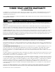
THREE YEAR LIMITED WARRANTY For Plasma Displays Congratulations on your purchase of a Runco video product and welcome to the Runco family! We believe Runco produces “The World’s Finest Home Theater Products.” With proper installation, setup and care, you should enjoy many years of unparalleled video performance. This is a LIMITED WARRANTY as defined in the Magnuson-Moss Warranty Act. Please read it carefully and retain it with your other important documents.
MOREOVER, DAMAGE RESULTING DIRECTLY OR INDIRECTLY FROM IMPROPER INSTALLATION OR SETUP IS SPECIFICALLY EXCLUDED FROM COVERAGE UNDER THIS LIMITED WARRANTY. IT IS IMPERATIVE THAT INSTALLATION AND SETUP WORK BE PERFORMED ONLY BY AN AUTHORIZED RUNCO DEALER TO PROTECT YOUR RIGHTS UNDER THIS WARRANTY. THIS WILL ALSO ENSURE THAT YOU ENJOY THE FINE PERFORMANCE OF WHICH YOUR RUNCO PRODUCT IS CAPABLE WHEN INSTALLED AND CALIBRATED BY RUNCO AUTHORIZED PERSONNEL.
ADDITIONAL INFORMATION: To locate the name and address of the nearest Runco Authorized Service Center, or for additional information about this Limited Warranty, please call or write: EL IM IN A R Y RUNCO INTERNATIONAL, INC.
Important Safety Instructions Thank you for your purchase of this quality Runco product! It has been designed to provide you with the quality of video that is expected in a home theater. This manual is your guide through the menus and operation. For the best performance, please read it carefully and keep it handy for future reference.
Compliance Information DECLARATION OF CONFORMITY: Manufacturer’s Name: Runco International, a subsidiary of Planar Systems, Inc.
FCC PART 15: NOTE: This equipment has been tested and found to comply with the limits for a Class B digital device, pursuant to Part 15 of the FCC Rules. These limits are designed to provide reasonable protection against harmful interference in a residential installation. • Reorient or relocate the receiving antenna. EL IM IN A R • Increase the separation between the equipment and receiver.
1 Table of Contents THREE YEAR LIMITED WARRANTY ............................................................................. iii Important Safety Instructions ........................................................................................ vi Compliance Information ............................................................................................... vii 1. Introduction ...............................................................................................................
Other Considerations ............................................................................................21 Connections to the PlasmaWall and DHD Controller ...................................................22 Connecting the PlasmaWall to the DHD Controller ................................................22 Connecting Source Components to the DHD Controller .......................................25 RS-232 Controller Connection ........................................................................
1 List of Figures 2-1. PlasmaWall XP-50DHD Front-Panel Controls and Indicators ........................................5 2-2. PlasmaWall XP-65DHD Front-Panel Controls and Indicators ........................................5 2-3. PlasmaWall XP-103DHD Front-Panel Controls and Indicators ......................................6 2-4. PlasmaWall Rear Panel.................................................................................................7 Y 2-5. DHD Controller Front Panel .......................
List of Figures PR EL IM IN A R Y Notes: xii PlasmaWall XP Series Owner’s Operating Manual
1. Introduction This Owner’s Manual describes how to install, set up and operate a Runco PlasmaWall XP Series Flat-Panel Plasma Display Monitor and DHD Controller (Model XP-50DHD, XP-50DHDxa, XP-65DHD, XP-65DHDxa or XP-103DHD). 1.1 About This Manual EL IM IN A R Y Throughout this manual, the Runco PlasmaWall XP Series Flat-Panel Plasma Display Monitor and DHD Controller are referred to collectively as the “PlasmaWall.
Introduction Graphic Conventions: These symbols appear in numerous places throughout the manual, to emphasize points that you must keep in mind to avoid problems with your equipment or injury: Note NOTES emphasize text with unusual importance or special significance. They also provide supplemental information. Caution CAUTIONS alert users that a given action or omitted action can degrade performance or cause a malfunction.
Introduction The PlasmaWall XP Series Flat-Panel Plasma Display Monitor and DHD Controller establish a higher threshold for flat panel display products. The PlasmaWall XP Series is available in three sizes, including our largest and highest-resolution plasma ever, at 103 inches diagonal and 1920 x 1080 (1080p) native resolution. 1.
Introduction Parts List ➤ Your PlasmaWall is shipped with the following items. If any items are missing or damaged, please contact your Runco dealer or Runco Customer Service at (800) 23-RUNCO. • PlasmaWall XP Series Flat-Panel Plasma Display Monitor and DHD Controller • AC Power Cords (2) • Remote Control Unit and two (2), AAA-size batteries • RJ-11 Telephone Cable, 50 feet (15.
2. Controls and Functions 2.1 PlasmaWall at a Glance 2 (behind front bezel) 4 3 EL IM IN A R Y Figure 2-1, Figure 2-2 and Figure 2-3 show the PlasmaWall front-panel controls and indicators. PR 1 Figure 2-1. PlasmaWall XP-50DHD Front-Panel Controls and Indicators 3 4 2 (behind front bezel) 1 Figure 2-2.
Controls and Functions 4 3 EL IM IN A R Y 2 1 Figure 2-3. PlasmaWall XP-103DHD Front-Panel Controls and Indicators 1. DISPLAY STAND Optional accessory for table-top installations. 2. POWER BUTTON Connects or disconnects the display panel from the AC power source. 3. STANDBY/ON INDICATOR - Lights green to indicate normal operation; - Lights red to indicate that the PlasmaWall is in standby mode. PR 4. REMOTE CONTROL SENSOR Receives the signals from the remote control.
Controls and Functions Figure 2-4 shows the rear-panel connector locations on the PlasmaWall. XP-50DHD Connectors EL IM IN A R Y 6 XP-65DHD PR 6 XP-103DHD NOTE: Some PlasmaWall models have a DVI-D input board installed in SLOT 2. A B AV IN 6 R AUDIO L PR/CR/R PB/CB/B Y/G AUDIO COMPONENT/RGB IN SLOT1 SLOT2 SLOT3 1 2 3 PC 4 Figure 2-4.
Controls and Functions 1. SLOT 1 Not used. 2. SLOT 2 (DVI-D or Dual HDMI input) HDCP-compliant digital video input(s). Connect the HDMI output from the DHD Controller to this input. If SLOT 2 is equipped with an Dual HDMI input board, connect the HDMI output from the DHD Controller to input “A” on this board. If SLOT 2 is equipped with a DVI-D input board, the audio input is not used. Connect the audio outputs from your sources to an external audio receiver.) Y 3. SLOT 3 Not used. EL IM IN A R 4.
Controls and Functions 4. VACUUM FLUORESCENT DISPLAY Can be used instead of the On-Screen Display (OSD). Displays currently-selected menu or – if no menu is selected – the current source, signal format (NTSC or PAL) and aspect ratio. 5. UP BUTTON Used to direct select aspect ratios or move the menu cursor up in the OSD. When no menu is present on-screen, the UP button toggles through aspect ratios in the following order: 16:9 - 4:3 - Letterbox - VirtualWide - Cinema EL IM IN A R Y 6.
Controls and Functions 2.3 DHD Controller Rear Panel Figure 2-6 shows the rear connector panel on the DHD Controller. 7 3 9 SYSTEM CONTROL INTERFACE CAUTION INPUTS Serial No R/Pr G/Y B/Pb RISK OF ELECTRIC SHOCK DO NOT OPEN H V TRIGGERS CAUTION: TO REDUCE THE RISK OF ELECTRIC SHOCK, DO NOT REMOVE COVER. NO USERSERVICEABLE PARTS INSIDE. REFER SERVICING TO QUALIFIED SERVICE CENTER.
Controls and Functions 8. ComLink (RS-232) OUTPUT Connect this to the ComLink (RS-232) input on the projector, using the provided communication cable. 9. IR Wired input from a wired remote control or infrared receiver. It is a 3.5-mm, mini phono jack, wired as follows: Ring = +5V Tip = IR Input Sleeve = Ground When an external remote control or infrared receiver is connected to the wired IR input, the IR sensor on the front of the DHD is disabled. Y Note EL IM IN A R 10.
Controls and Functions 2.4 DHD Controller Remote Control Figure 2-7 shows the DHD Controller remote control, and the paragraphs that follow describe its functionality. 2 Y 1 EL IM IN A R 4 (not available on some models) 5 RETURN EXIT 6 8 16 : 9 11 4:3 3 7 9 12 PR 13 HDMI 1 10 HDMI 2 14 CUST 1 THX SVC (“CUST 2” on some models) Figure 2-7.
Controls and Functions 1. IR OUTPUT INDICATOR Lights when a button is pressed to indicate that an IR signal is being transmitted. 2. ON / OFF Press to turn the PlasmaWall on or off. 3. ENTER Press to select a highlighted menu item or confirm a changed setting. 4. Cursor Keys ( , , , ) Use these buttons to select items or settings, adjust settings or switch display patterns.
Controls and Functions 10. Aspect Ratio Selection Buttons Use the red buttons to select an aspect ratio directly or to enter numeric characters, as follows: 16 : 9 (3) For viewing 16:9 DVDs or HDTV programs in their native aspect ratio. 4 : 3 (6) Scales the input signal to fit 4:3 display mode in the center of the screen. Y LETBOX (Letterbox) (9) For viewing LaserDisc movies or non-anamorphic DVDs on a 16:9 screen.
3. Installation 3.1 Remote Control To install batteries in the remote control: EL IM IN A R Y 1. Press down the tab on the cover and pull the cover in the direction of the arrow. 2. Insert the included batteries. Ensure that the polarities correctly match the and markings inside the battery compartment. 3. Insert the lower tab of the cover into the opening, and press down the cover until it clicks in place. • When installing batteries, make sure that the battery polarities are correct.
Installation • Do not drop the remote control or expose it to moisture or high temperature. • The remote control may malfunction under a fluorescent lamp. If that occurs, move the plasma display away from the fluorescent lamp. • Make sure that there is nothing obstructing the infrared beam between the remote control and the IR receiver on the plasma display. Note The signal from the remote control can be reflected by walls or other surfaces.
Installation Table 3-1 gives a quick overview of the PlasmaWall installation process. The sections following this one provide detailed instructions. Note Installation should be performed by a qualified custom video installation specialist. For Details, refer to page... Procedure EL IM IN A R Step Y Table 3-1.
Installation 3.3 Installation Considerations Proper installation of your PlasmaWall will ensure the highest possible picture quality. Whether you are installing the PlasmaWall temporarily or permanently, you should take the following into account to ensure that it performs optimally.
Installation You can attach your optional mounts or stand to the PlasmaWall in either of two ways: EL IM IN A R Y • While it is upright. • As it lies flat with the screen face down. Place the protective sheet, which was wrapped around the plasma monitor when it was packaged, between the screen and your work surface to avoid scratching or otherwise damaging the screen surface. PR In general, minimize or eliminate light sources directed at the display.
Installation Wall 50mm (2") 50mm (2") Wall 50mm (2") 50mm (2") EL IM IN A R Y 50mm (2") Figure 3-2. Ventilation Requirements for Enclosure Mounting (XP-50DHD and XP-65DHD) 300mm (11.8") 300mm (11.8") PR 300mm (11.8") 300mm (11.8") Wall Wall 200mm (7.87") Figure 3-3.
Installation Here are some other considerations and tips that can help improve your installation, avoid damage and prolong operating life: • Keep the ambient temperature constant and below 35°C (95°F). Keep the display away from heating and/or air conditioning vents. Changes in temperature may cause drifts in the display circuitry, which may affect performance. • Keep the PlasmaWall away from devices that radiate electromagnetic energy such as motors and transformers.
Installation 3.4 Connections to the PlasmaWall and DHD Controller Proceed as follows to connect the PlasmaWall to the DHD Controller, your video sources, external controller(s) – if present – and AC power. When connecting your equipment: • Turn off all equipment before making any connections. • Use the correct signal cables for each source. • Ensure that the cables are securely connected. Tighten the thumbscrews on connectors that have them.
Installation PlasmaWall Rear Panel R AUDIO AUDIO Optional Terminal Board Insert Slot (covered) PR/CR/R PB/CB/B Y/G COMPONENT/RGB IN SLOT2 SLOT3 AUDIO EL IM IN A R SLOT1 L DVI-D IN PC IN SYSTEM CONTROL INTERFACE INPUTS Serial No R/Pr G/Y B/Pb SERIAL CAUTION RISK OF ELECTRIC SHOCK DO NOT OPEN H V ! AVIS: RISQUE DE CHOC ELECTRIQUE-NE PAS OUVRIR TRIGGERS HD1 1 Model Y (XP-65DHD shown here) 2 IR 3 CAUTION: TO REDUCE THE RISK OF ELECTRIC SHOCK, DO NOT REMOVE COVER.
Installation Digital Video Connection: The PlasmaWall has a dual HDMI input board, labeled HDMI (SLOT 2). Connect the HDMI output from the DHD Controller to input “A” on this board, using an HDMI-to-HDMI cable. Some PlasmaWall XP Series models have a DVI input board (labeled DVI-D IN (SLOT 2)) in place of the dual HDMI input board. Connect the HDMI output from the DHD Controller to this input, using a DVI-to-HDMI cable or equivalent cable/adapter combination.
Installation Connect your video sources to the DHD Controller as shown and described in the sections that follow. HDMI Connections: See Figure 3-7. Use the HDMI inputs whenever possible. This ensures the highest video quality because the signal is carried in the digital domain throughout the entire signal path, from source component output into the projector.
Installation Digital (DTV) RGB Connections: See Figure 3-8. R/Pr G/Y INPUTS B/Pb H V TRIGGERS HD1 1 2 3 HD2 R/Pr G/Y B/Pb H V S-Video 1 Pb HDMI 2 Pr Y Component Video Video S-Video 2 EL IM IN A R Y HDMI 1 PR Red/Pr Green/Y Blue/Pb Horiz Vert DTV or Progressive Component (YPbPr) Source Figure 3-8.
Installation Analog (Computer) RGB Connections: See Figure 3-9. 1. Refer to PlasmaWall Specifications on page 61 for a list of computer signals compatible with the PlasmaWall. Use with signals other than those listed may cause some functions not to work. Note 2. Some Macintosh computers may require a Macintosh video adapter. Contact your nearest authorized service center or dealer.
Installation Composite/S-Video/Component Video Connections: See Figure 3-10. R/Pr G/Y INPUTS B/Pb H V TRIGGERS HD1 1 2 3 HD2 R/Pr G/Y B/Pb H V S-Video 1 HDMI 2 Pb Y Pr Component Video Video S-Video 2 EL IM IN A R Y HDMI 1 PR Pb Pr Y DVD Player, VCR, Satellite Receiver, Laser Disc etc. Figure 3-10.
Installation Use a standard, 9-pin RS-232 cable to connect a PC or home theater control/automation system (if present) to the RS-232 Control port on the DHD Controller; see Figure 3-11. RS-232 Controller Connection For more information about using this connection, refer to Serial Communications on page 55.
Installation Connecting an External IR ➤ Receiver to the DHD Controller If infrared signals from the remote control cannot reach the DHD Controller due to excessive distance or obstructions such as walls or cabinet doors, you can connect an external IR receiver to the DHD Controller to extend the range of the remote control. See Figure 3-13.
Installation Plug the female end of the power cord into the AC receptacle on the rear of the PlasmaWall. Connect the other end to your AC power source. (The XP-103DHD requires 200-240 VAC.) XP-65DHD EL IM IN A R Y XP-50DHD PR XP-103DHD (NOTE: The XP-103DHD requires 200 - 240 VAC) Figure 3-14. AC Power Connection Similarly connect the DHD Controller to a nearby AC outlet.
Installation Cable Management ➤ To reduce cable clutter, use the cable clamps provided with the PlasmaWall to bundle the video, audio and control cables at the back of the display. Install the clamps as shown in Figure 3-15. Securing the AC cord to the rear of the panel (XP-50DHD) 2. Insert the AC cord and close the clamp securely. 1. Open the clamp. Clamp 4. Insert the end of the clamp band into the small hole on the lower right of the back cover. 3. Slide the clamp upward to secure the AC cord.
4. Operation 1. Turn on your source components. 2. Press the main power switch on the PlasmaWall (see Figure 2-1, Figure 2-2 or Figure 2-3). The standby/on indicator lights green. 4.1 Turning on the Power 3. Set the main power switch at the rear of the DHD Controller (see Figure 2-6) to the “on” position. EL IM IN A R Y 4. Press the ON button on the remote control to turn on the DHD Controller and PlasmaWall (or press the power button on the front of the DHD Controller).
Operation 2. Double click on the Display icon. 3. Click the Settings tab on the display dialog box. EL IM IN A R Y 4. Set the Screen area to 1024x768 pixels. PR 5. Click the Advanced button and click the Monitor tab on the dialog box. Set the Refresh Frequency to 60Hz and click OK. Note 1. The native resolution of the PlasmaWall is 1920 x 1080. Other horizontal or vertical resolutions may be scaled upward or downward to fit the display. 2.
Operation Press the MENU button on either the remote control or the DHD Controller front panel to display the Main Menu. To select a menu item, use the UP ( ) and DOWN ( ) buttons on either the remote control or the DHD Controller front panel to highlight it. Press ENTER to confirm your selection. The PlasmaWall OSD menus are arranged hierarchically, as shown in Figure 4-1. Depending on the selected input source and signal characteristics, some menu options may not be available.
Operation Picture Input Position Memory Presets Information PR (read-only) ISF Night - Input Image ISF Night - Input Color Y Aspect Ratio ISF Night - Display Color EL IM IN A R Input Source Composite S Video 1 S Video 2 Component SD HD/RGB 1 HD/RGB 2 HDMI 1 HDMI 2 16:9 4:3 Letterbox VirtualWide Cinema Brightness Contrast Color Tint Sharpness Left/Right Up/Down Width Height Overscan Recall ISF Night Recall ISF Day Recall or Save Custom 1 Recall or Save THX/Custom 2 Reset Custom 1 and THX/Custom
Operation The Main Menu is the starting point for accessing all display functions. Main Menu (The Calibration and Service menus are hidden and not accessible until you enter a passcode.) Runco Video Input Source Aspect Ratio Picture Input Position ISF Presets Information Calibration EL IM IN A R From the Main Menu, select Input Source to choose a video signal source. Y Service The active source is indicated by an arrow (>) to its left; in this example, Composite is the active source.
Operation Table 4-1. Aspect Ratio Settings Aspect Ratio Remote Control Key 16:9 16:9 Description Select 16:9 to view 16:9 DVDs and HDTV programs in their native aspect ratio. EL IM IN A R Y 16:9 Image on 16:9 Screen (Display) 4:3 images are stretched horizontally to fit a 16:9 screen.
Operation Use the controls in the Picture Menu to calibrate the analog inputs on the PlasmaWall for optimum picture quality. Picture Picture Note To calibrate the digital (HDMI 1 and HDMI 2) inputs, use the Display Image controls in the Service menu. For more information, refer to Display Device on page 48. Brightness Contrast Color Tint EL IM IN A R Y The PlasmaWall has been designed to incorporate setup and calibration standards established by the Imaging Science Foundation (ISF).
Operation PLUGE patterns vary but generally consist of some combination of black, white and gray areas against a black background. The example above includes two vertical bars and four shaded boxes. Select Brightness from the Picture menu and press ENTER. Adjust the brightness so that: • The darkest black bars disappear into the background. • The dark gray areas are barely visible. • The lighter gray areas are clearly visible. • The white areas are a comfortable level of true white.
Operation EL IM IN A R Y blue red magenta green cyan yellow gray Color Saturation: On your external test pattern source, select a color bar pattern like the one shown in Figure 4-4. Figure 4-4. Typical Color Bar Pattern for Adjusting Color Saturation and Tint blue red magenta green cyan PR yellow gray Select Color and press ENTER.
Operation EL IM IN A R Y Sharpness: “Sharpness” is the amount of high-frequency detail in the image. To adjust sharpness, select Sharpness from the Picture menu and press ENTER. On your external test pattern source, select a pattern like the one shown in Figure 4-5. Adjust as needed, looking for white edges around the transitions from black to gray and differently-sized lines in the “sweep” patterns at the top and bottom. Lower the sharpness setting to eliminate them. Figure 4-5.
Operation Overscan: Image Overscan pushes the outside edge of the active picture area of the video signal out beyond the edge of the display area. Some television programs are produced based on the assumption that older television sets may not display the outer edges of the broadcast picture area. Over scan effectively trims away these inactive, outer edges and enlarges the remaining portion of the image to fill the display area. Select from 1% to 10% of Overscan, as desired.
Operation Calibration ➤ Use the Calibration menu to perform advanced picture quality adjustments on the analog inputs. This menu should be used by ISF-certified technicians only. Calibration ISF Night Note Display Color Input Image Input Color Note ISF Day To calibrate the digital (HDMI 1 and HDMI 2) inputs, use the Display Image controls in the Service menu. For more information, refer to Display Device on page 48. You must enter a passcode to access the Calibration menu.
Operation ISF Night - Input Color: The Input Color controls are similar to those in the Display Color menu (see above), but adjust the color balance at the DHD Controller (as opposed to the display device). These settings are also saved independently for each input. • Gain/Offset: These controls operate similarly to those in the ISF Night - Display Color menu (see above), but affect the Y, Pb and Pr signal components rather than the red and blue channels.
Operation • Runco/ISF Logo Splash Screen Timers: When you turn on the PlasmaWall, it projects a welcome screen with the Runco logo followed by one with the ISF logo. Select Splash Timer from the Splash Configure menu to set the amount of time that these two images appear. The range is from 2 to 60 seconds, in one-second increments. Use the up or down cursor button to select a timer value to adjust. Use the right or left cursor button to change the timer value.
Operation Remote Control: The Remote Control menu shows you the primary and secondary infrared (IR) codes to which the DHD Controller will respond. By default, both are set to 17. You can change these codes if either: • Another device in the theater (a DVD player, for example) is responding to commands from the DHD Controller remote control (Figure 2-7) in ways that are unpredictable or undesirable. Note Use the DHD Controller front-panel keypad to change its IR code.
Operation Display Device: The options in the Display Device menu allow you to perform certain adjustments at the plasma display. • Display Position: Select Display Position from the Display Device menu to perform the following display device adjustments (these are global, independent of any input): • Select Left/Right or Up/Down and use the displayed image position. • Select Width or Height and use the aspect ratio.
Operation HD Format: If the characteristics of the incoming signal on the HD1 or HD2 inputs are known, select HD Format from the Service menu and set them as described below. Doing so can reduce the time it takes the DHD Controller to switch from HD to 480i signals or vice versa. This is generally not necessary unless the DHD Controller – for whatever reason – has difficulty determining the color space (RGB or YUV), bandwidth or resolution of the incoming HD signal.
Operation System Reset: To reset ALL DHD Controller settings (including image settings) back to their factory defaults, choose System Reset from the Service menu. A confirmation message appears, reminding you to save your settings before you perform the reset, so that you can restore them afterwards. If you have done this, select Confirm to continue with the reset. Otherwise, click Back to cancel. This action is not undoable.
5. Maintenance and Troubleshooting Regular cleaning will extend the life and performance of the PlasmaWall. Before cleaning, be sure to unplug the power cord from the power outlet. Do not under any circumstances use solvents such as benzene or thinner to clean the PlasmaWall. Doing so may cause deterioration or peeling of paint from the display or remote control unit. 5.
Maintenance and Troubleshooting 5.2 Troubleshooting Tips Table 5-1 provides some general guidelines for troubleshooting problems you may encounter with the PlasmaWall. If the suggested solutions fail to resolve the problem or if you encounter an issue not described here, please contact your Runco dealer or Runco Technical Support. Table 5-1. Troubleshooting Chart Symptom Possible Cause(s) • The PlasmaWall is not plugged in or the AC outlet is not active.
Maintenance and Troubleshooting Table 5-1. Troubleshooting Chart (continued) Symptom Possible Cause(s) Solution • Clock and Phase settings need adjustment. • Adjust Clock and Phase settings (refer to ISF Night - Input Color on page 45). Computer images do not display correctly. • The resolution and frequency of the video card in the computer are not compatible with the PlasmaWall. • Select a compatible resolution and vertical frequency (refer to PlasmaWall Specifications on page 61).
Maintenance and Troubleshooting PR EL IM IN A R Y Notes: 54 PlasmaWall XP Series Owner’s Operating Manual
6. Serial Communications To interface the PlasmaWall with a home theater automation/control system or a PC running terminal emulation software, connect it to the RS-232 output of the DHD Controller as shown in Figure 3-5. Connect your control system or PC to the RS-232 input of the DHD Controller as shown in Figure 3-11. 6.
Serial Communications Table 6-1 lists the RS-232 command set. The “Parameter (min/max)” column shows the valid parameter ranges, or “NA” for commands that take no parameters. When you enter a valid command, the DHD Controller executes it and acknowledges it with a plus sign on the command line (+ >). When you enter an invalid command – one that is misspelled or followed by values outside the valid range for that command – the DHD Controller ignores it and returns a minus sign (- >). Table 6-1.
Serial Communications Table 6-1.
Serial Communications Table 6-1.
Serial Communications Table 6-1.
Serial Communications Table 6-1. Serial Commands (continued) Parameter (min/max) Command Value Stored? Description The following serial commands are meant to emulate buttons on the remote control or DHD Controller front panel. Each button has its own serial command, so effectively it is as if you were using the IR remote only you’ll be doing so via serial commands. These commands provide active OSD responses just like the IR remote.
7. Specifications 7.1 PlasmaWall Specifications Table 7-1 lists the PlasmaWall specifications. Table 7-1. PlasmaWall Specifications 1920 x 1080 Screen Size: XP-50DHD / XP-50DHDxa: 43.50 in. W x 24.50 in. H (1104.9 x 622.3 mm) 50 in. (1270.0 mm) diagonal XP-65DHD / XP-65DHDxa: 56.50 in. W x 31.80 in. H (1434.0 x 807.0 mm) 65 in. (1646.0 mm) diagonal XP-103DHD: 89.30 in. W x 50.30 in. H (2268.2 x 1277.6 mm) 103 in. (2616.
Specifications Table 7-1. PlasmaWall Specifications (continued) Limited Warranty: Three (3) years parts and labor from the date of delivery to the end user (except for plasma glass panel). Plasma Glass Panel: One (1) year parts and labor from the date of delivery to the end user. Regulatory Approvals: Complies with FCC Part 15 Class B, ICES-003, UL6500 Ver.2 Table 7-2 lists the DHD Controller specifications. EL IM IN A R PR 7.
Specifications 4.566 EL IM IN A R 34.000 50.420 30.000 Y Figure 7-1, Figure 7-2 and Figure 7-3 show the PlasmaWall dimensions (all dimensions are in inches). 8.122 15.500 3.490 PR 22.828 22.042 20.293 16.136 14.387 10.230 8.481 0 48.807 30.000 29.574 Figure 7-1. PlasmaWall Model XP-50DHD Dimensions (with Optional Table Stand) PlasmaWall XP Series Owner’s Operating Manual 63 7.
Specifications 37.5 35.0 18.7 2.5 1.1 0 1.7 17.0 7.0 0 2.5 7.4 8.8 10.0 65.4 EL IM IN A R Y 31.2 4.5 59.8 62.3 2.1 4.1 5.6 2.1 37.5 30.4 25.1 12.0 9.0 0 1.7 PR 4.5 0 2.3 10.3 18.5 43.0 52.3 60.0 62.3 Figure 7-2.
Specifications EL IM IN A R 59.500 102.500 Y 50.750 87.875 89.375 96.125 69.000 5.375 PR 11.875 5.250 33.000 21.500 12.625 16.625 40.000 0.375 Figure 7-3.
Specifications 7.4 Supported Timings Table 7-3 lists the signal types supported by each input on the DHD Controller. Table 7-3. Supported Signal Timings by Input 800x600 1024x768 60.00 31.469 25.175 √ 72.00 37.861 31.500 √ 75.00 37.500 31.500 √ 85.00 43.269 36.000 56.00 35.156 60.00 800x600 1024x768 Video – – – – – – – – – – – √ – – – – 36.000 √ – – – – 37.879 40.000 √ √ – – – 72.00 48.077 50.000 √ √ – – – 75.00 46.875 49.
Specifications Table 7-3. Supported Signal Timings by Input (continued) Format Resolution PAL-B/G – PAL-M – PAL-N – PAL-60 – Refresh Rate (Hz) Horizontal Frequency (kHz) 50.00 15.625 59.94/60.00 15.734/15.750 50.00 15.625 59.94/60.00 15.734/15.750 Supported? (√ = Yes, – = No) Pixel Frequency HD/RGB 1 HDMI 1 S-Video 1 (MHz) Component HD/RGB 2 HDMI 2 S-Video 2 4.430 √ – √ √ √ 3.580 √ – √ √ √ 3.580 √ – √ √ √ 4.
Specifications PR EL IM IN A R Y Notes: 68 PlasmaWall XP Series Owner’s Operating Manual
SERIAL NUM BER 020-0726-00 rev. A (RUMA-009825) November 2007 Runco International • 2900 Faber Street • Union City, CA 94587 • Ph (510) 324-7777 / (800) 23RUNCO / Fax (510) 324-9300 www.runco.