I NSTALLATION/ O PERATION M ANUAL LS-HB High-Brightness, Full-HD Home Theater Projector
RuncoCare™ Standard Two Year Limited Warranty Congratulations on your purchase of a Runco® product! With proper installation, setup and care, you should enjoy many years of unparalleled video performance. Y This RuncoCare Standard Limited Warranty is provided free of charge by Runco International, LLC (“Runco”) with the purchase of a covered Runco product.
RuncoCare Claim Procedure In the event of a product defect, please follow the warranty claim procedure provided below: 1. The Customer is required to contact a Runco dealer or Runco Technical Support via email at support@runco.com or via phone at (toll free) (800) 23RUNCO (800-237-8626). If the customer is located outside North America, call +3589 4200 554 in Europe for product service. 2.
h Expected lamp degradation and normal decrease in lamp output over a period of time or as the lamp is consumed i Customer caused defects, including but not limited to, scratched/defaced/altered plastics j Failure to follow maintenance procedures as outlined in the product’s user guide where a schedule is specified for regular cleaning of the product k Opening the product and/or tampering with internal circuitry l Products lost, stolen or discarded m Any damage or dissatisfaction associated with laten
Online Product Registration Please visit http://www.runco.com/support/product-registration/ to register product. Limitation of Implied Warranties Y RUNCO PROVIDES NO WARRANTIES, EXPRESS OR IMPLIED, EXCEPT THOSE EXPRESSLY PROVIDED HEREIN. RUNCO EXPRESSLY DISCLAIMS ALL OTHER WARRANTIES, INCLUDING THE IMPLIED WARRANTIES OF MERCHANTABILITY AND FITNESS FOR A PARTICULAR PURPOSE.
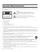
Important Safety Instructions Thank you for your purchase of this quality Runco video product! It has been designed to provide you with the quality of video that is expected in a home theater. For the best performance, please read this manual carefully as it is your guide through the menus and operation. 1. Read these instructions. 2. Keep these instructions. 3. Heed all warnings. 4. Follow all instructions.
19. Never look directly into the lens when the lamp is on.
FCC PART 15: NOTE: This equipment has been tested and found to comply with the limits for a Class B digital device, pursuant to Part 15 of the FCC Rules. These limits are designed to provide reasonable protection against harmful interference in a residential installation. • Reorient or relocate the receiving antenna. EL IM IN A R • Increase the separation between the equipment and receiver.
PR EL IM IN A R Y Notes: x Runco LS-HB Installation/Operation Manual
1 Table of Contents RuncoCare™ Standard Two Year Limited Warranty ................................................... iii Important Safety Instructions ....................................................................................... vii Compliance Information .............................................................................................. viii 1. Introduction ...............................................................................................................
Table of Contents Mounting the LS-HB ..................................................................................................27 Floor Mounting (Upright) .......................................................................................27 Ceiling Mounting (Inverted)....................................................................................27 Installing the Projector in an Enclosure ..................................................................27 Adjusting the Projection Angle ...
Table of Contents 5. Maintenance and Troubleshooting ........................................................................71 Lamp Replacement ....................................................................................................71 Troubleshooting Tips ..................................................................................................72 6. Serial Communications ..........................................................................................
Table of Contents PR EL IM IN A R Y Notes: xiv Runco LS-HB Installation/Operation Manual
1 List of Figures 2-1. LS-HB Front/Side View ................................................................................................5 2-2. LS-HB Rear/Bottom/Top View .....................................................................................7 2-3. LS-HB Rear Panel ........................................................................................................9 3-1. IR Reception Angles ...............................................................................................
List of Figures 4-15. LS-HB Service Menu ................................................................................................68 PR EL IM IN A R Y 7-1. LS-HB Dimensions .....................................................................................................
Introduction 1. Introduction This Owner’s Manual describes how to install, set up and operate the Runco LS-HB Digital Light Processing (DLP™) Projector. 1.1 About This Manual Throughout this manual, the Runco LightStyle™ Series LS-HB Home Theater Projector is referred to as the “LS-HB.” Target Audience Y Runco has prepared this manual to help home theater installers and end users get the most out of the LS-HB.
Introduction Graphic Conventions: These symbols appear in numerous places throughout the manual, to emphasize points that you must keep in mind to avoid problems with your equipment or injury: Note NOTES emphasize text with unusual importance or special significance. They also provide supplemental information. Caution CAUTIONS alert users that a given action or omitted action can degrade performance or cause a malfunction.
Introduction Elegant and electrifying, the LightStyle™ Series LS-HB Home Theater Projector is Runco’s first-ever 1080p projector designed for both performance and esthetics. Where sleek design encompasses incredible performance, this stylish combination of legendary Runco engineering and impactful design yield a powerhouse that elevates the bar for affordable home theater projection.
Introduction Key Features and Benefits ➤ The LS-HB offers these key features and benefits: • Native Resolution: 1920 x 1080 (16:9 Native Aspect Ratio) • DLP system using high-performance Digital Micromirror Device (DMD) • Customized color wheel produces wide dynamic range and rich grayscale • Picture in Picture function allows you to display two inputs on the screen at the same time • Two (2), HDMI Inputs with High-bandwidth Digital Content Protection (HDCP) • HDTV Compatible Your LS-HB is shipped with th
Controls and Functions 2. Controls and Functions 2.1 LS-HB at a Glance Figure 2-1 and Figure 2-2 show the key LS-HB components. Top IR Sensor Intake Vent Front IR Sensor Y Exhaust Vent (on side) EL IM IN A R System Keypad Power Button/ Status LED Focus Ring Projection Lens Zoom Ring Figure 2-1. LS-HB Front/Side View PR • TOP IR SENSOR Receives infrared signals from the remote control unit.
Controls and Functions • ZOOM RING Rotate this to change the projected image size. • FRONT IR SENSOR Receives infrared signals from the remote control unit. • INTAKE VENT Internal fans draw cool air into the projector through this vent. • SYSTEM KEYPAD Provides an alternative to using the remote control unit to select a source or navigate the on-screen display (OSD) controls. SOURCE ▲ ► ▲ Cursor Keys ( , , , ) Use these buttons to select items or settings, adjust settings or switch display patterns.
Controls and Functions 3 EL IM IN A R 2 PR 4 5 Y 1 6 7 Figure 2-2.
Controls and Functions 1. RUNCO LOGO BADGE Remove to access the vertical lens shift control. Y 2. REAR COVER Remove to access connectors. Vertical Lens Shift EL IM IN A R 3. LAMP MODULE COVER Remove this cover to access the lamp compartment. 4. CABLE OPENING Pass cables through this opening. 5. CEILING MOUNT HOLES Use these to attach the ceiling bracket to the projector. Use M4 screws with a maximum screw depth of 10 mm (0.39 inch). 6.
Controls and Functions 2.2 LS-HB Rear Panel Figure 2-3 shows the LS-HB rear panel. 8 7 6 4 5 1 EL IM IN A R Y 9 2 3 Figure 2-3. LS-HB Rear Panel PR 1. HDMI 1 (Digital) HDMI 2 (Digital) HDCP-compliant digital video inputs for connecting an HDMI or DVI source. 2. RGB Provides a standard, 15-pin VGA-style connection to either an RGB or component high-definition source, or to a personal computer. The LS-HB automatically detects the input signal resolution. 3.
Controls and Functions 7. IR INPUT Wired input from a Niles- or Xantech-compatible, infrared (IR) repeater system. 8. TRIGGER 1 (3.5-mm, mini phono jack) Provides 12 (+/- 1.5) volt switched output for screen relays with 250mA current capacity and short protection. PR 3. Source Selection Buttons (1-5): Press to select a video source. By default, these buttons are assigned as follows: 1 = HDMI 1; 2 = HDMI 2; 3 = Component 1; 4 = S-Video; 5 = Video.
Controls and Functions 5. Aspect Ratio Selection Button Press this button repeatedly to select one of the following aspect ratios: 16 : 9: For viewing 16:9 DVDs or HDTV programs in their native aspect ratio. Letterbox: For viewing LaserDisc movies or non-anamorphic DVDs on a 16:9 screen. 4 : 3: Scales the input signal to fit 4:3 sources in the center of the screen. 4:3 Narrow: Scales the input signal to fit 4:3 sources in the center of the screen when using an anamorphic lens.
Controls and Functions PR EL IM IN A R Y Notes: 12 Runco LS-HB Installation/Operation Manual
Installation 3. Installation To install batteries in the remote control: 1. Slide the battery compartment cover in the direction of the arrow to remove it. 3.1 Remote Control 2. Install two AA batteries with the correct polarity. 3. 2. EL IM IN A R 1. Y 3. Replace the cover. • Make sure that the battery polarities are correct when installing the batteries. Notes on Batteries • Do not mix an old battery with a new one or different types of batteries.
Installation • The projector’s front IR receiver has a range of approximately 40 feet (12.19 meters); the top IR receiver has a range of approximately 20 feet (6.10 meters). Figure 3-1 shows the reception angles of the front and top IR receivers. EL IM IN A R Y 90.0° 90.0° 135.0° PR Figure 3-1.
Installation Table 3-1 gives a quick overview of the LS-HB installation process. The sections following this one provide detailed instructions. Note Installation should be performed by a qualified custom video installation specialist. For Details, Refer to page... Procedure EL IM IN A R Step Y Table 3-1.
Installation 3.3 Installation Considerations Proper installation of your projector will ensure the quality of your display. Whether you are installing a projector temporarily or permanently, you should take the following into account to ensure your projector performs optimally. Installation Type ➤ Choose the installation type that best suits your needs: front or rear screen, floor mount or inverted mount. Table 3-2 compares these various installation methods. Table 3-2.
Installation In general, minimize or eliminate light sources directed at the screen. Contrast ratio in your images will be noticeably reduced if light directly strikes the screen, such as when a shaft of light from a window or floodlight falls on the image. Images may then appear washed out and less vibrant. Ambient Light Throw distance is the distance measured from the front of the projector to the screen.
Installation Table 3-3 lists the available LS-HB lens options and their associated throw ratios. Table 3-3. LS-HB Lens Options and Throw Ratios (Note) LS-HB + Standard Lens 1.89 – 2.40 LS-HB + Standard Lens + Fixed Anamorphic Lens Throw Range in inches, with 72.6x40.8-inch (1.78:1) Screen Throw Ratio Throw Range in with inches, with Primary 96x40.8-inch (2.35:1) Lens and Screen Anamorphic Minimum Maximum Minimum Maximum Lens 137.21 EL IM IN A R (n/a) 174.
Installation Ceiling Installation Height Ceiling Projection Distance x Lens Center Lens Center Screen Screen EL IM IN A R Height Y Floor Installation Lens Center Lens Center x Projection Distance Floor Figure 3-3. Projector Placement PR You can use the lens shift controls on the projector to center the image on the screen. Lens shift is generally expressed as a percentage of the screen height or width, as shown in Figure 3-4. Screen Center 0% 50% Height Lens Shift (0.
Installation 1. With no vertical lens shift, the lens center and screen center are aligned with each other. Note 2. Vertical shift limits are percentages of the screen height. 3. Vertical lens shift figures are for ceiling mount configurations. For floor installations (where the projector is upright), reverse the up/down vertical lens shift percentages. In rear-screen applications where space behind the projector is limited, a mirror may be used to fold the optical path, as shown in Figure 3-5.
Installation If you are installing a standard LS-HB (without an anamorphic lens), skip this step and proceed with Mounting the LS-HB (page 27). If you are installing an LS-HB with a fixed anamorphic lens, proceed with Installing the Fixed Anamorphic Lens Base Plate (page 26). 3.4 Installing the Optional Anamorphic Lens Mount Note EL IM IN A R Y If you are installing an LS-HB with a movable anamorphic lens, proceed as follows to install the lens mount and transport assembly. 1.
Installation • Anamorphic lens and mounting bracket Y Attaching the Transport Assembly Attachment Plate: 1. Place the projector upside down on a blanket or other soft surface. EL IM IN A R 2. Position the attachment plate as shown here.
Installation 3. If you are mounting the projector on a ceiling: Line up the holes on the Ceiling Mount Plate (included with the projector ceiling mount kit) with those on the bottom of the projector and attachment plate. 4. Secure the Transport Assembly Attachment Plate and Ceiling Mount Plate to the projector using the hardware provided with the attachment plate, as shown. Caution 1. Do not use the mounting screws provided with the ceiling mounting kit.
Installation Installing the Anamorphic Lens Transport Assembly: After installing the Transport Assembly Attachment Plate and Ceiling Mount Plate, proceed as follows to install the Anamorphic Lens Transport Assembly.
Installation Attaching the Security Hooks: To help stabilize and support the added weight of the Anamorphic Lens and Lens Transport Assembly, the attachment plate includes two security hooks and related hardware for attaching the front part of the plate to the ceiling above. Proceed as follows to attach the security hooks. This requires the following tools and materials: • Pliers • Scissors EL IM IN A R Y • Ceiling Hooks (not supplied) 1.
Installation Installing the Fixed ➤ Anamorphic Lens Base Plate To install the base plate on an LS-HB with a fixed anamorphic lens: 1. Place the projector upside down on a blanket or other soft surface. 2. Secure the base plate and Ceiling Mount Plate (if used) to the projector with the four, M4 x 0.7 x 14mm screws provided with the anamorphic lens base plate. Caution 1. Do not use the mounting screws provided with the ceiling mounting kit.
Installation There are several methods for mounting the projector. Depending on your chosen installation, one method may be more suitable than another. 3.5 Mounting the LS-HB Floor Mounting (Upright) For fixed installations, and for those that want the projector out of sight or have a limited space for projector and audience, you can invert the LS-HB and suspend it from the ceiling using a specially-designed ceiling mount fixture.
Installation Adjusting the Projection ➤ Angle If the screen is significantly higher or lower than the projector, you can also tilt the projector at a slight angle. In a ceiling installation, you do this by adjusting the ceiling mount. For a floor installation, turn the adjustable feet at the bottom of the projector to adjust the projection angle. EL IM IN A R Y The projector can be rotated (side-to-side) up to 360 degrees and mounted without it affecting performance.
Installation Proceed as follows to connect the LS-HB to your video sources, external controller(s) – if present – and AC power. When connecting your equipment: 3.6 Connections to the LS-HB • Use the correct signal cables for each source. • Ensure that the cables are securely connected. Tighten the thumbscrews on connectors that have them. Connector Panel Access EL IM IN A R Y Using a flat-blade screwdriver, loosen the two screws holding the rear compartment cover in place.
Installation Connecting Source ➤ Components to the LS-HB Connect your video sources to the LS-HB as shown and described in the sections that follow. HDMI/DVI Connections: See Figure 3-8. Use the HDMI inputs whenever possible. This ensures the highest video quality because the signal is carried in the digital domain throughout the entire signal path, from source component output into the projector.
Installation Computer EL IM IN A R Y RGBHV Connections: Connect your personal computer or other RGB source to the RGB input. See Figure 3-9. RGB Camcorder PR or Figure 3-9.
Installation Red Blue Green Sync EL IM IN A R Y SCART RGBS Connection: If the source outputs RGB with composite sync, connect the green, blue and red outputs to the Y, Pb and Pr terminals on the COMPONENT 1/SCART input and the sync output to the VIDEO input. See Figure 3-10. VCR SCART-to-RGBS adapter PR DVD/DTV STB Sync Green Blue Red Gaming Console Figure 3-10.
Installation PR EL IM IN A R Y Component Video Connections: Connect your component video sources to the COMPONENT 1/SCART or RGB inputs as shown in Figure 3-11. COMPONENT VIDEO OUT Y PB BD/DVD PR DTV-Set-Top Box (DTV-STB) Figure 3-11.
Installation S-Video VCR Composite EL IM IN A R Y Composite/S-Video Connections: Connect your Composite and S-Video sources to the LS-HB as shown in Figure 3-12. S-Video Camcorder Composite PR Gaming Console Figure 3-12.
Installation Connect a PC or home theater control/automation system (if present) to the RS-232 port on the LS-HB; see Figure 3-13. Use a standard, 9-pin serial cable, wired straight-through. EL IM IN A R Y For more information about using this connection, refer to Serial Communications on page 75. 5 4 9 to Automation/ Control System or PC 3 8 1 2 7 6 2 Transmit Data 3 Receive Data 5 Ground (none of the other pins are used) PR Figure 3-13.
Installation Connecting 12-Volt ➤ Trigger Output to External Theater Equipment If your LS-HB is equipped with a movable anamorphic lens, OR if your home theater contains a retractable screen, screen mask or other 12-volt trigger-activated equipment, connect these devices to the TRIGGER 1 output as shown in Figure 3-14. +12V Trigger Input PR EL IM IN A R Y 3.5-mm mini plug Retractable Screen or other 12-volt trigger-activated device Sleeve = Ground Tip = +12V Figure 3-14.
Installation Connecting an External IR Receiver LIGHT NR M3 SHARP Y MEMOR M2 USER SWAP OS M1 EL IM IN A R (3.
Installation 3.7 Turning on the Power 1. Turn on your source components. ON 2. Press the ON l button on the remote control to turn on the LS-HB. The LED flashes green to indicate that it is warming up. 3. When the projector is ready for use, the LED turns off. 3.8 Primary Lens Adjustments To focus the projected image, grasp the lens by the front ring and rotate it. EL IM IN A R Focus and Zoom ➤ Y The LS-HB gives you a great deal of control over the picture size, position and focus.
Installation When you turn on the LS-HB for the first time, the OSD Language Menu appears. or to select a language. Then, press ENTER to confirm your selection. PR Press EL IM IN A R Y The LS-HB can display the menus in English, French, German, Italian, Spanish, Swedish, Traditional Chinese, Simplified Chinese, Japanese, Korean, Portuguese or Russian. 3.9 Changing the OSD Language If the LS-HB is installed behind the screen, you must change the picture orientation to match the installation method.
Installation 3.11 Installing and Adjusting the Anamorphic Lens If you are installing an LS-HB with an anamorphic lens, proceed as follows to install and adjust that lens. It is extremely important that the primary lens is properly adjusted before you install the anamorphic lens. Ensure that the image from the primary lens is perfectly centered on the screen. Note The fixed anamorphic lens mount kit consists of everything shown in Figure 3-16.
Installation 1. Use the Height/Pitch Adjustment Screws (3) and Washers (2) to attach the Lens Mounting Bracket (5) to the Anamorphic Lens (1). 2. Remove the nut and rubber collar from each Swell Latch Assembly (4). 3. Secure the lens (with the mounting bracket attached) to the Lens Base Plate (6) using the swell latches. Tip To avoid clipping the corners of the image, position the anamorphic lens as close as possible to the primary lens. Y Adjusting the Lens Height and Angle: 1.
Installation 4. Then, adjust the anamorphic lens angle so that the projected image is rectangular: EL IM IN A R Incorrect Lens Angle Y Correct Lens Angle The anamorphic lens will almost always be angled with respect to the projector; this is normal. 5. When the height and angle are properly set, tighten the Height/Pitch Adjustment Screws to secure the lens in place. Note Attach the movable anamorphic lens to the bracket using the plastic knobs supplied with the lens. See Figure 3-17.
Installation 2. Tighten the knobs. Note There may be some pincushion distortion even after the lens is properly adjusted, especially at shorter throw distances. If this is the case, Runco recommends that you slightly over-scan the image into the screen frame area to mask the distortion. 3. Adjust the rotation of the Lens Transport Assembly so that the left and right sides of the image are an equal distance from their respective screen borders. Y 4.
Installation PR EL IM IN A R Y Notes: 44 Runco LS-HB Installation/Operation Manual
Operation 4. Operation Press M1, M2 or M3 to recall settings from a memory preset. Then, press ENTER to confirm your selection. Or, to cancel the operation, press to select Cancel and press ENTER. You can assign each of these three buttons to any of four memory presets. For more information, refer to M1 Key / M2 Key / M3 Key on page 66. 4.
Operation For PIP purposes, there are three groups of inputs 4.4 separated by their display modes: Using Picture-In-Picture (PIP) • Video (SD) group: Video, S-Video and SCART PIP SWAP LIGHT inputs. • Graphic (HD) group: Component 1 and RGB inputs. • Digital Video group: HDMI 1 and HDMI 2 inputs. PIP shows one input from any of these groups within or beside one input from either of the other two groups. Y • Press PIP to enable the PIP function.
Operation 1. Press the MENU button on the remote control or system keypad to display the Main Menu. 2. There are six menus. Press 3. Press or or to select a sub-menu. 4.5 Using the On-Screen Menus to select a sub-menu item. 4. For each sub-menu item, the currently-selected value appears in white text or is otherwise highlighted. Press or to choose a setting for that item, or press ENTER to go to another sub-menu. 6. From the Main Menu, press MENU to turn off the OSD menu. Y 5.
Operation Main ➤ The LS-HB Main Menu, shown in Figure 4-2, provides access to the most commonly-used projector functions. Image controls only operate on the active source. To adjust the PIP source, switch to the PIP source (thereby making it the active source), adjust the controls and then switch back. PR EL IM IN A R Y Note Figure 4-2.
Operation Aspect Ratio: To change the aspect ratio (size and shape) of the projected image, press or to highlight Aspect Ratio. Use the or buttons to select the appropriate aspect ratio for your screen size, installed lens configuration and the type of program material being viewed, then press ENTER; refer to Table 4-2. Table 4-2. Aspect Ratio Settings Aspect Ratio of Source Signal Description Geometry of Projected Image With Standard Lens (1.78:1 Screen) With Anamorphic Lens (2.
Operation Table 4-2. Aspect Ratio Settings (continued) Aspect Ratio Setting Aspect Ratio of Source Signal Description Geometry of Projected Image With Standard Lens (1.78:1 Screen) With Anamorphic Lens (2.35:1 Screen) 16:9 Y EL IM IN A R Letterbox Letterbox mode scales (zooms in on) a 4:3 image linearly (by the same amount on all sides) to fill a 16:9 display, cropping the top and bottom of the image.
Operation Table 4-2. Aspect Ratio Settings (continued) Aspect Ratio of Source Signal Description Native With Standard Lens (1.78:1 Screen) With Anamorphic Lens (2.35:1 Screen) 1080i HDTV Image 1080i HDTV Image 16:9 EL IM IN A R Select Native to display the source signal in its native resolution, centered in the display area with no re-sizing or overscan.
Operation Memory: Select Memory from the Main menu, then press ENTER to recall image quality settings previously saved, or to save changed settings in any of four memory locations. • Recall Memory: Select Recall Memory from the Memory menu to recall saved image quality settings. Unless you select Default (see below), this control affects all sources, not just the active source. • User Memory 1 and User Memory 2 contain the factory default settings when the projector is initially turned on.
Operation Above Black EL IM IN A R Below Black Y Brightness: On your external test pattern source, select a PLUGE pattern. (PLUGE is an acronym for “Picture Line-Up Generation Equipment.”) Figure 4-3 shows a typical PLUGE pattern. Figure 4-3. Typical PLUGE Pattern for Adjusting Brightness PLUGE patterns vary but generally consist of some combination of black, white and gray areas against a black background. The example above includes two vertical bars and four shaded boxes.
Operation Note Brightness and Contrast controls are interactive. A change to one may require a subtle change to the other in order to achieve the optimum setting. Color: To adjust the overall color intensity, select Color from the Main menu. Decrease this setting if colors are overly saturated; increase it if colors appear muted or washed out. Like the Brightness and Contrast controls, the color and tint controls are interactive.
Operation • Sharpness Mode: Sharpness Mode allows or prevents access to the detailed sharpness controls in this menu. In most cases, Simple mode provides a sufficient level of control to produce the best picture from the most popular sources. In Simple mode, only the Sharpness (top-most) slider is adjustable; the others are grayed out. Choose Advanced mode if you need more precise control over sharpness. In Advanced mode, only the top slider is grayed out.
Operation Overscan: Some television programs are produced based on the assumption that older television sets may not display the outer edges of the broadcast picture area. Overscan effectively hides these inactive, outer edges of the image. Choose one of the following: • Off: This setting leaves the image as-is.
EL IM IN A R Y Operation Figure 4-7. Source Select Sub-Menu PIP Select: To select a PIP (secondary) video source, press Select, then press ENTER. The default PIP selection is Off. or to highlight PIP PR All sources that are not available per the source enable function (refer to Source Enable on page 63) are grayed out. All sources that cannot be used for PIP due to a shared electronic path with the Active source are grayed out.
Operation Use the controls in the Advanced menu, shown in Figure 4-8, to perform advanced image adjustments. EL IM IN A R Y Advanced ➤ Figure 4-8. LS-HB Advanced Menu PR Color Space: Select Color Space from the Advanced menu to choose the color space of the source signal for HDMI, RGB, and component connections. • The default setting, Auto, functions as follows: • HDMI: If the Auxiliary Video Information (AVI) infoframe contains color space and/or range data, the LS-HB uses that information.
Operation Video Standard: Select Video Standard from the Advanced menu to specify the color system for composite video or S-Video input signals. Different countries use different formats for video signals. Select the appropriate Video Standard for your region: • Auto: The color systems are automatically identified and the format is set accordingly. • PAL: This is the standard used in Europe, Australia and many other parts of the world, typically with a 50Hz frame rate.
Operation EL IM IN A R Y RGB Adjust: To remove any trace of color from the white areas of the projected image, choose RGB Adjust from the Advanced menu and press ENTER. This displays the RGB Adjust sub-menu, shown in Figure 4-9. PR Figure 4-9. RGB Adjust Sub-Menu • Gain: Use the Gain controls to correct color imbalances in the bright areas of the image. A good way to do this is to use a test pattern consisting mostly of solid white areas, such as an 80 IRE “window” pattern.
Operation EL IM IN A R Y Fine Sync: To fine-tune the position and other image attributes, choose Fine Sync from the Advanced menu and press ENTER. This displays the Fine Sync sub-menu, shown in Figure 4-10. Figure 4-10. Fine Sync Sub-Menu PR • V Position: This control adjusts the vertical position of the image within the designated image area, up to 25 per cent of the image height up or down.
Operation is consistent across the screen, that aspect ratio is maintained and that pixel phase (see above) can be optimized. • Sync Level (Component sources only): Select Sync Level to adjust the voltage level of the LS-HB Sync signal detection circuitry. Sync Level adjustment is occasionally necessary when a DVD player or HDTV source signal drops “below black” (for example, during scenes with explosions or when subtitles are present) and causes the projector to temporarily lose sync.
Operation EL IM IN A R Y Source Enable: To enable or disable selection of a source, choose Source Enable from the System menu and press ENTER. This displays the Source Enable sub-menu, shown in Figure 4-12. Figure 4-12. Source Enable Sub-Menu PR • HDMI 1/HDMI 2: Enables or disables the HDMI 1 and HDMI 2 sources. • RGB: Enables or disables the RGB source. • Comp 1: Enables or disables the Component 1 source. • Video: Enables or disables the Composite video source.
Operation PIP Position: To change the position of the PIP image, choose PIP Position from the System menu; see Figure 4-13. Choose one of the following: • Top Left: This places the PIP source into a 644x362 designated image area at the top left of the screen. • Top Right: This places the PIP source into a 644x362 designated image area at the top right of the screen. • Bottom Left: This places the PIP source into a 644x362 designated image area at the bottom left of the screen-safe area of the DMD.
EL IM IN A R Y Operation Figure 4-14. PIP Split-Screen Mode Menu Position: Select Menu Position from the System menu to change the OSD menu position. The default setting is “ “ (top left). Translucent Menu: Select Translucent Menu from the System menu to adjust the degree of translucence (show-through) in the menus and message boxes. 0% means that the menus are opaque. The default setting is 25%.
Operation Select Control from the Main Menu to set various options related to control of the projector. EL IM IN A R Y Control ➤ PR 1 Key / 2 Key / 3 Key / 4 Key / 5 Key: These menu items assign the function of the keys numbered 1 through 5 on the remote. There are eight sources corresponding to the eight connections to the projector. When you assign a source to a numbered key, the projector immediately goes to that source when the key assigned to it is pressed.
Operation • RS232 causes the port to output 12 volts when an RS232 screen trigger 1 “on” command is received and stop when a trigger 1 “off” command is received. The 12 volt output also stops when the projector is turned off. Remote Code Set: Select Remote Code Set from the Control menu to specify the remote IR code set to which the LS-HB responds. The default is Set-1.
Operation Service ➤ Access the Service Menu, shown in Figure 4-15, to view information that uniquely identifies your projector and indicates its current operational status: • Model Name • Unit Serial Number • Software Version • Active/PIP Source • Pixel Clock • Signal Format • H/V Refresh Rate Y • Lamp Hours (number of lamp hours elapsed since the last reset) PR EL IM IN A R Should you ever need to contact Runco Technical Support, this information will help them answer your questions and/or resolve p
Operation Lamp Hour Reset: When you replace the projector lamp (refer to Lamp Replacement on page 71), you should also reset the lamp hour counter. To do this, select Lamp Hour Reset from the Service menu, then press ENTER. Press ENTER again to confirm the reset. Or, to cancel the operation, press on the remote to highlight No, then press ENTER. Reset the Lamp Hour counter ONLY after you replace the lamp. Otherwise, the reported “Lamp Hours” will be inaccurate.
Operation To turn test patterns off, press any key other than built-in keypad. or on the remote control unit or Altitude: Select Altitude from the Service Menu to control the operation of the projector’s cooling fan. PR EL IM IN A R Y In most cases, the default setting (Auto) will maintain the correct operating temperature. If the lamp frequently turns off due to overheating, or in certain high-altitude operating environments, you may need to change this setting to High.
Maintenance and Troubleshooting 5. Maintenance and Troubleshooting The lamp should be replaced when it reaches the end of its life (typically 2000 hours), or sooner if a noticeable degradation in brightness occurs. Contact your Runco dealer to obtain a replacement lamp. Y 1. Turn off the projector and unplug the power cord. Allow the projector to cool down for approximately 60 minutes prior to removing the lamp assembly for replacement. EL IM IN A R 2.
Maintenance and Troubleshooting 5.2 Troubleshooting Tips Table 5-1 provides some general guidelines for troubleshooting problems you may encounter with the LS-HB. If the suggested solutions fail to resolve the problem or if you encounter an issue not described here, please contact Runco Technical Support. Table 5-1. Troubleshooting Chart Symptom Solution • The LS-HB is not plugged in or the AC outlet is not active. • Lamp cover is not securely attached.
Maintenance and Troubleshooting Table 5-1. Troubleshooting Chart (continued) Symptom Possible Cause(s) Solution • The Red/Pr, Green/Y or Blue/Pb outputs from the source are connected to the wrong inputs on the LS-HB. • Ensure that the source outputs are connected to the correct LS-HB input. LED is flashing alternating green and red. • The lamp cover is open. • The lamp has failed or exceeded its usage life. • Close the lamp cover. • Replace the lamp with a new one. LED is flashing red.
Maintenance and Troubleshooting PR EL IM IN A R Y Notes: 74 Runco LS-HB Installation/Operation Manual
Serial Communications 6. Serial Communications To interface the LS-HB with a home theater automation/control system or a PC running terminal emulation software: 1. Connect it to your control system or PC as shown in Figure 3-13. 6.1 RS-232 Connection and Port Configuration 2. Start a terminal session on your PC using a terminal-emulation program, such as HyperTerminal. Y 3. Configure the RS-232 controller or PC serial port as follows: 38400 bps, no parity, 8 data bits, 1 stop bit and no flow control.
Serial Communications Table 6-1 lists the serial command key names and IR codes. Table 6-1. Serial Command Key Names and IR Codes IR Code Remote Button Description Set 1 Set 2 pow.on l 0x01 0xB7 Turn power on. src.sw (none) 0x02 0xB8 Switch to the next source. 0x09 0xB9 Turn power off. 0x15 Y RS232 Keyname pow.off 0xBA EL IM IN A R menu Bring up or cancel menu display. MENU enter 0x17 0xBB Keypad enter. 0x18 0xBC Keypad down arrow. 0x1A 0xBD Keypad up arrow.
Serial Communications Table 6-1. Serial Command Key Names and IR Codes (continued) RS232 Keyname IR Code Remote Button Description Set 1 Set 2 (none) 0x86 0xC6 Switch to CRT gamma (2.5). gam.film (none) 0x87 0xC7 Switch to Film gamma (2.2). gam.vide (none) 0x88 0xC8 Switch to Video gamma. gam.brig (none) 0x89 0xC9 Switch to Bright Room gamma (2.0). src.1 1 0x8B 0xCB Switch the active source to source 1. src.2 2 0x8C 0xCC Switch the active source to source 2. src.
Serial Communications Table 6-1. Serial Command Key Names and IR Codes (continued) RS232 Keyname IR Code Remote Button Description Set 1 Set 2 (none) 0x9F 0xDF Apply 4:3 aspect ratio to the active source. asp.lett (none) 0xA0 0xE0 Apply Letterbox aspect ratio to the active source. asp.narr (none) 0xA1 0xE1 Apply 4:3 Narrow aspect ratio to the active source. 0xA3 0xE3 Switch to next “PIP Select” state. 0xE4 Change “PIP Select” to source 1. pip.sw PIP Y asp.4.3 (none) 0xA4 pip.
Serial Communications Table 6-2 lists the valid operations commands. For all but Execute functions, the response from the projector is the command and “= ” where is the current value or “NA” if the value is not available. For Execute functions the response is the same command. All responses are in UPPERCASE.
Serial Communications Table 6-2. Serial Commands (continued) Operation Commands Values = 0 = ISF Day 1 = ISF Night bright contrast saturat tint sharp.simple = ? + - 0 - 200 sharp.mode = ? 0 = Simple 1 = Advanced PR EL IM IN A R Y save.isf Notes horiz.sharp vert.sharp diag.sharp sharp.over horiz.text vert.text diag.text text.over noise.thresh = ? + - 0 - 200 nr.simple = ? + - 0 - 200 nr.mode = ? 0 = Simple 1 = Advanced nr.general = ? + - 0 - 200 block.
Serial Communications Table 6-2. Serial Commands (continued) Commands Values (execute) color.space = ? 0 = Auto 1 = REC709 2 = REC601 3 = RGB-PC 4 = RGB-Video video.stand = ? 0 = Auto 1 = NTSC 2 = PAL 3 = SECAM gamma = ? dlp.frame = ? satco = ? red.off green.off blue.off red.gain green.gain blue.gain = ? + - EL IM IN A R resync Notes Y Operation 0 = CRT (2.5) 1 = Film (2.2) 2 = Video 3 = Bright (2.
Serial Communications Table 6-2. Serial Commands (continued) Operation Commands Values = ? 0 = 0% 1 = 25% 2 = 50% 3 = 75% blank.screen = ? 0 = Black 1 = Blue 2 = White 3 = Logo auto.pow.off = ? 0 = Off 1 = On PR EL IM IN A R Y trans.menu Notes auto.pow.on = ? 0 = Off 1 = On rear.proj = ? 0 = Off 1 = On ceil.mode = ? 0 = Off 1 = On 2 = Auto power.chime = ? 0 = Off 1 = On 1.key 2.key 3.key 4.key 5.
Serial Communications Table 6-2. Serial Commands (continued) Commands Values ? act.source pip.source ? 0 = HDMI 1 1 = HDMI 2 2 = RGB 3 = YPrPb 1 5 = S-video 6 = Video 7 = SCART h.refresh ? v.refresh ? pixel.clock ? signal ? lamp.hours ? total.hours ? environment ? (execute) fact.reset (execute) blue.only = language PR lamp.reset pattern kHz EL IM IN A R soft.
Serial Communications Table 6-2. Serial Commands (continued) Operation Commands Values Notes status ? 0 = Standby 1 = Powering Up 2 = Displaying 3 = Cooling Down 4 = Error errcode ? Refer to RS-232 Error Codes, below. msgbox = ? 0 = On 1 = Off EL IM IN A R Y This control enables or disables the display of power off, source and adjustment message boxes (brightness, contrast etc.). Default value is ON. PR cal.text1 cal.text2 cal.text3 RS-232 Error Codes = Up to 30 characters.
Serial Communications Table 6-3. RS-232 Error Codes (continued) LED Indication Description Fan 1 failed. 8 Fan 2 failed. 9 Fan 3 failed. 10 Fan 4 failed. 11 Fan 5 failed. 12 Fan 6 failed. 16 17 18 19 20 21 22 23 24 25 DDP3021 communication failure upon system power-up. Lamp failed to ignite (three attempts) upon system power-up. Lamp failed during operation. Ballast UART communication failure. PCF8575 external GPIO communication failure. Lamp door is open.
Serial Communications PR EL IM IN A R Y Notes: 86 Runco LS-HB Installation/Operation Manual
Specifications 7. Specifications 7.1 LS-HB Specifications Table 7-1 lists the LS-HB specifications. Table 7-1. LS-HB Specifications Signal Compatibility HDMI and DVI with HDCP for digital video, Component and RGB HDTV (1080p, 1080i, 720p), Component and RGB EDTV (576p, 480p), Component, Composite and S-Video SDTV (576i, 480i), RGB SCART with adapter, NTSC/NTSC 4.
Specifications Table 7-1.
Specifications Table 7-1. LS-HB Specifications (continued) General 20.8" (530mm) L x 17.9" (455mm) W x 7.8" (200mm) H (see Figure 7-1) Weight (without lens): 24.3 lbs. (11.00 kg) Operating Temperature: 50°F to 95°F (10°C to 35°C) Operating Altitude: Sea Level - 10,000 feet (3,048m) Operating Humidity: 0% to 85% non-condensing Universal Power Supply: 100V - 240V at 50-60Hz (auto-ranging), true soft power Power Consumption: 400 Watts (1365.
Specifications 7.2 LS-HB Dimensions Figure 7-1 shows the LS-HB dimensions, in millimeters. IM IN A R 530 Y 200 PR EL 455 LENS CENTER LINE 135 80 APPROXIMATE CENTER OF GRAVITY 150 75 160 CEILING MOUNT HOLES M4 x 10mm MAXIMUM (4x) Figure 7-1.
Specifications 7.3 Supported Timings Table 7-2 lists the signal types supported by each input on the LS-HB. Table 7-2. Supported Signal Timings by Input 800x600 640x480 800x600 Supported? (√ = Yes, – = No) Refresh Rate (Hz) Horizontal Frequency (kHz) Pixel Frequency (MHz) RGB Component HDMI 1 HDMI 2 Composite S-Video 60.00 31.469 25.175 √ – √ – 66.59 35.892 29.862 √ – √ – 75.00 37.500 31.500 √ – √ – 85.00 43.269 36.000 √ – √ – 60.00 37.879 40.000 √ – √ – 75.
Specifications Table 7-2. Supported Signal Timings by Input (continued) Format Resolution Supported? (√ = Yes, – = No) Refresh Rate (Hz) Horizontal Frequency (kHz) Pixel Frequency (MHz) RGB Component HDMI 1 HDMI 2 Composite S-Video 50.00 56.250 148.500 √ √ √ – 148.350/148.500 √ √ √ – 1080/50p 1920x1080 1080/60p 1920x1080 59.94/60.00 67.433/67.500 – 59.94/60.00 15.734/15.750 3.580 – – – √ NTSC 4.43 – 59.94/60.00 15.734/15.750 4.
020-1093-00 Rev. A November 2010 Runco International • (800) 23RUNCO • Fax (503) 748-8161 • www.runco.