O W N E R ’S O P E R A T I N G M A N U A L CL-410 CL-420 DLP™ Projectors
TWO YEAR LIMITED WARRANTY For Projectors, Video Processors and Controllers Congratulations on your purchase of a Runco video product and welcome to the Runco family! We believe Runco produces “The World’s Finest Home Theater Products.” With proper installation, setup and care, you should enjoy many years of unparalleled video performance. This is a LIMITED WARRANTY as defined in the Magnuson-Moss Warranty Act. Please read it carefully and retain it with your other important documents.
EFFECTIVE WARRANTY DATE: This warranty begins on the effective date of delivery to the end user. For your convenience, keep the original bill of sale as evidence of the purchase date. IMPORTANT -- WARRANTY REGISTRATION: Please fill out and mail your warranty registration card. It is imperative that Runco knows how to reach you promptly if we should discover a safety problem or product update for which you must be notified.
ADDITIONAL INFORMATION: To locate the name and address of the nearest Runco Authorized Service Center, or for additional information about this Limited Warranty, please call or write: RUNCO INTERNATIONAL, INC.
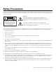
Safety Precautions Thank you for your purchase of this quality Runco video projector! It has been designed to provide you with the quality of video that is expected in a home theater. For the best performance, please read this manual carefully as it is your guide through the menus and operation. CAUTION RISK OF ELECTRIC SHOCK DO NOT OPEN CAUTION: TO REDUCE THE RISK OF ELECTRIC SHOCK DO NOT REMOVE COVER (OR BACK) NO USER SERVICEABLE PARTS INSIDE. REFER SERVICING TO QUALIFIED SERVICE PERSONNEL.
1 Table of Contents TWO YEAR LIMITED WARRANTY ................................................................................. iii Safety Precautions ......................................................................................................... vi 1. Introduction ...............................................................................................................1 About This Manual .......................................................................................................
Table of Contents Connections to the CL-410/CL-420 ...........................................................................20 Connector Panel Access.......................................................................................20 Connecting the CL-410/CL-420 to Source Components ......................................20 RS-232 Controller Connection ..............................................................................25 Connecting to the 12-Volt Trigger Output ............................
1 List of Figures 2-1. CL-410/CL-420 Top/Front/Side View ...........................................................................5 2-2. CL-410/CL-420 Rear/Top/Side View............................................................................6 2-3. CL-410/CL-420 Remote Control ..................................................................................8 3-1. Available Range of the Remote Control ......................................................................12 3-2.
List of Figures Notes: x Runco CL-410 and CL-420 Owner’s Operating Manual
1. Introduction This Owner’s Manual describes how to install, set up and operate the Runco CL-410 and CL-420 DLP Projectors. Throughout this manual, the Runco CL-410 and CL-420 DLP Projectors are referred to collectively as the “CL-410/CL-420.” The information in this manual applies to both projectors except where otherwise indicated. Runco has prepared this manual to help home theater installers and end users get the most out of the CL-410/CL-420. 1.
Introduction Graphic Conventions: These symbols appear in numerous places throughout the manual, to emphasize points that you must keep in mind to avoid problems with your equipment or injury: 1.2 Using This Manual Tip TIPS highlight time-saving short cuts and helpful guidelines for using certain features. Note NOTES emphasize text with unusual importance or special significance. They also provide supplemental information.
Introduction The Runco CL-410 and CL-420 DLP Projectors combine a highly efficient optical light engine with broad installation and integration options. Runco has implemented a host of advancements into the projector’s light engine to take full advantage of its widescreen, high-definition SuperOnyx™ Digital Micromirror Device (DMD™) chip. The CL-410/CL-420 features Enhanced GEN 3™ technology to produce deeper blacks, greater contrast ratio and brightness, and richly saturated colors. 1.
Introduction Parts List ➤ Your CL-410/CL-420 is shipped with the following items. If any items are missing or damaged, please contact your Runco dealer or Runco Customer Service at (800) 23-RUNCO. • CL-410 or CL-420 DLP Projector • AC Power Cord (North America) • AC Power Cord (Europe) • Remote Control Unit and two (2), AAA-size batteries • HD 15-pin VGA to HD 15-pin VGA cable • DVI-D to DVI-D cable • DVI-to-HDMI adapter • Composite video cable (RCA) • +12-Volt Trigger adapter (3.
2. Controls and Functions Figure 2-1 and Figure 2-2 show the locations of key CL-410/CL-420 projector components. 1 Front/Top/Side View 2 11 10 9 8 7 6 5 2.1 CL-410/CL-420 at a Glance 4 3 Figure 2-1. CL-410/CL-420 Top/Front/Side View 1. TOP IR SENSOR 2. VERTICAL LENS SHIFT DIAL Shifts the image up or down. 3. INTAKE VENT 4. ADJUSTABLE FEET Use to adjust the height or projection angle. 5. RUNCO LOGO The logo can be rotated to match the projector orientation: inverted (ceiling-mounted) or upright.
Controls and Functions 7. FOCUS/ZOOM RING 8. EXHAUST VENT 9. HORIZONTAL LENS SHIFT DIAL 10. TEMPERATURE INDICATOR Flashes blue when the projector is overheated. 11. POWER INDICATOR Lights solid blue when the projector is in standby mode; flashes blue during cool-down. During normal operation, this LED is off.
Controls and Functions 1. COMPOSITE VIDEO INPUT Standard composite video input for connecting a VCR, camcorder, laser disc player or other composite video source. 2. S-VIDEO Standard S-Video input for connecting a DVD player, satellite receiver or Super VHS (S-VHS) VCR. 3. COMPONENT VIDEO (RCA connectors) Standard-definition (480i/576i) or high-definition (720p/1080i), YPrPb component input. This is the input for component video from sources such as DVD players.
Controls and Functions 2.2 CL-410/CL-420 Remote Control Figure 2-3 shows the CL-410/CL-420 remote control, and the paragraphs that follow describe its functionality. 1 2 4 3 7 5 6 8 9 12 10 11 Figure 2-3. CL-410/CL-420 Remote Control 1. IR OUTPUT INDICATOR Lights when a button is pressed to indicate that an IR signal is being transmitted. 2. ON / OFF Press to turn the projector on or off. 3.
Controls and Functions 6. LIGHT Press this button to illuminate the buttons. 7. MENU Press this button to access the on-screen display (OSD) controls. 8. Source Selection Buttons: VIDEO Press to switch to the Composite video input. COMP 1 (Component 1) Press to switch to the Component 1 (480i/576i/720p/1080i) video input. RGB HD Press to switch to the RGB HD input. S-VID 1 (S-Video) Press to switch to the S-Video input.
Controls and Functions Notes: 10 Runco CL-410 and CL-420 Owner’s Operating Manual
3. Installation 3.1 Remote Control To install batteries in the remote control: 1. Press down the tab on the cover and pull the cover in the direction of the arrow. 2. Insert the included batteries. Ensure that the polarities correctly match the and markings inside the battery compartment. 3. Insert the lower tab of the cover into the opening, and press down the cover until it clicks in place. • When installing batteries, make sure that the battery polarities are correct.
Installation Notes on Remote Control ➤ Operation The remote control can be used to control the projector within the ranges shown in Figure 3-1. Figure 3-1. Available Range of the Remote Control Note The signal from the remote control can be reflected by the screen or other surfaces. • For best results, hold the remote control within 23 feet (7m) of the back or top sensor and aligned within 30°. • Do not drop the remote control or expose it to moisture or high temperature.
Installation Table 3-1 gives a quick overview of the CL-410/CL-420 installation process. The sections following this one provide detailed instructions. Note Installation should be performed by a qualified custom video installation specialist. Table 3-1. Installation Overview Step For Details, refer to page...
Installation 3.3 Installation Considerations Installation Type ➤ Proper installation of your projector will ensure the quality of your display. Whether you are installing a projector temporarily or permanently, you should take the following into account to ensure your projector performs optimally. Choose the installation type that best suits your needs: front or rear screen, floor mount or inverted mount. Table 3-2 compares these various installation methods. Table 3-2.
Installation Throw distance is the distance measured from the front of the projector to the screen. This is an important calculation in any projector installation as it determines whether or not you have enough room to install your projector with a desired screen size and if your image will be the right size for your screen. You can quickly estimate the throw distance by taking the width of the screen and multiplying it by the lens throw ratio; see Figure 3-2.
Installation Vertical and Horizontal ➤ Position Proper placement of the projector relative to the screen will yield a rectangular, perfectly-centered image that completely fills the screen. Ideally, the projector should be positioned perpendicular to the screen and in such a way that the lens center and screen center are aligned with each other, as shown in Figure 3-3.
Installation 150% Width Lens Shift (1.5 x W) 100% Width Lens Shift (1.0 x W) 50% Width Lens Shift (0.5 x W) Screen Center 0% Screen Width (W) Note: This is a general example of lens shift. Lenses vary in their shift capabilities. No particular lens or projector is shown in this example. Figure 3-5.
Installation Table 3-3 gives the lens shift limits for the CL-410 and CL-420, as percentages and absolute measurements with a 96 x 54 inch (1.78:1) screen. Table 3-3. Vertical and Horizontal Lens Shift Limits CL-410 CL-420 Lens Shift Limits, as Percentages of Screen Height or Width (Notes 1 and 2) Vertical (Notes 2 and 3) Horizontal (Note 2) Up 40% 46% Down 60% 63% Left 8% Right 8% Lens Shift Limits in Inches, with a 96-by-54 inch (1.78:1) Screen Up 21.60 24.84 Down 32.40 34.
Installation There are several methods for mounting the projector. Depending on your chosen installation, one method may be more suitable than another. Mounting Floor Mounting: In typical front and rear screen installations the projector can be mounted to a secure and level surface, such as a table or cart. Carts are useful when moving a projector during a presentation or from site to site. If possible, lock the wheels when it’s in position to prevent it from being moved during a presentation.
Installation 3.4 Connections to the CL-410/CL-420 Proceed as follows to connect the CL-410/CL-420 to your video sources, external controller(s) -- if present -- and AC power. When connecting your equipment: • Turn off all equipment before making any connections. • Use the correct signal cables for each source. • Ensure that the cables are securely connected. Tighten the thumbscrews on connectors that have them.
Installation COMP 2 PR/CR PB/CB PB/CB PR/CR Y COMP 2 Y PB/CB Y RGB-HD Y PR/CR RGB-HD PB/CB PR/CR S-VIDEO HDMI HDMI COMP 1 VIDEO VIDEO S-VIDEO COMP 1 RS-232 RS-232 HDMI or DVI Source (DVD Player or HD Set Top Box) Note: To connect a DVI source, use the HDMI-to-DVI adapter and DVI cable provided with the projector. Figure 3-7.
Installation RGB-HD Connections: The CL-410/CL-420 has an RGB input for connecting a personal computer or DTV decoder with an RGB output. See Figure 3-8. COMP 2 PR/CR PB/CB Y RGB-HD HDMI PB/CB PR/CR Y COMP 2 Y PB/CB Y PB/CB PR/CR RGB-HD PR/CR S-VIDEO HDMI COMP 1 VIDEO VIDEO S-VIDEO COMP 1 RS-232 RS-232 Personal Computer Figure 3-8. Analog RGB Connections Note 1. Refer to Computer Signal Compatibility on page 58 for a list of computer signals compatible with the CL-410/CL-420.
Installation Component Video Connections: If you have a DVD player or DTV decoder with a component (YPbPr) output, connect it to the COMP 1 or COMP 2 input as shown in Figure 3-9. COMP 2 PR/CR PB/CB PB/CB PR/CR Y COMP 2 PB/CB Y RGB-HD HDMI Y PB/CB Y PR/CR RGB-HD PR/CR S-VIDEO HDMI COMP 1 VIDEO VIDEO S-VIDEO COMP 1 RS-232 RS-232 Pr/Cr Pb/Cb Y Component Video Source (DVD Player or HD Set Top Box) Figure 3-9.
Installation Composite/S-Video Connections: The CL-410/CL-420 has S-Video and composite video inputs for connecting a DVD player, VCR, satellite receiver, camcorder, laser disc player et cetera; see Figure 3-10. COMP 2 PR/CR PB/CB PB/CB Y COMP 2 Y PR/CR PB/CB Y RGB-HD HDMI Y PB/CB PR/CR RGB-HD PR/CR S-VIDEO HDMI COMP 1 VIDEO VIDEO S-VIDEO COMP 1 RS-232 RS-232 Composite S-Video DVD Player, VCR, Satellite Receiver etc. Figure 3-10.
Installation Use a standard, 9-pin RS-232 cable to connect a PC or home theater control/automation system (if present) to the RS-232 port on the CL-410/CL-420; see Figure 3-11. For more information about using this connection, refer to Serial Communications on page 53.
Installation If your home theater contains a retractable screen or other, 12-Volt trigger-activated equipment, connect it to the 12-volt trigger output on the CL-410/CL-420 as shown in Figure 3-12. COMP 2 PR/CR PR/CR Y PB/CB PB/CB Y PB/CB COMP 2 PB/CB PR/CR Y RGB-HD HDMI Y PR/CR S-VIDEO RGB-HD COMP 1 VIDEO HDMI VIDEO S-VIDEO COMP 1 RS-232 RS-232 Connecting to the 12-Volt ➤ Trigger Output Retractable Screen or other, 12-volt trigger-activated equipment 3.
4. Operation 4.1 Turning on the Power 1. Turn on your source components. 2. Plug the female end of the power cord into the AC receptacle on the rear of the CL-410/CL-420 (AC 100V ~ 240V). 3. Connect the other end to your AC power source. The power indicator lights blue to indicate that the CL-410/CL-420 is in “standby” mode. 4. Press the ON button on the remote control to turn on the projector. The power indicator turns off. 5.
Operation 4.3 Changing the OSD Language The CL-410/CL-420 OSD language is initially set to English, but can also display the menus in French, Italian, German or Spanish. To change the OSD language: 1. Press MENU. 2. Select Installation from the Main Menu. 3. Select Language from the Installation Menu. 4. Press 4.4 Adjusting the Picture Orientation or to select the desired language. The change takes effect immediately.
Operation The CL-410/CL-420 gives you a great deal of control over the picture size, position and focus. Figure 4-2 shows the location of the focus and zoom controls; Figure 4-3 shows the location of the lens shift controls. To focus the projected image, rotate the focus ring left or right. To make the picture larger (zoom in), rotate the zoom ring to the left, toward the Runco logo. To make the picture smaller (zoom out), rotate the zoom ring to the right.
Operation Shift ➤ To change the projected image position, rotate the vertical and/or horizontal lens shift dials. Caution Do not force the lens shift dials beyond their respective ranges. This may cause the projector to malfunction. Lens shift dial (Horizontal) Lens shift dial (Vertical) Figure 4-3. Vertical and Horizontal Lens Shift Controls 4.6 Using the On-Screen Menus To use the on-screen menus: 1. Press MENU to display the Main Menu. 2.
Operation Picture Adjust Brightness Contrast Color Tint Sharpness Gamma Color Temp ICC Select White Balance Source Select Aspect Ratio Save Settings Restore Picture Settings Video S-Video Component 1 Component 2 RGB-HD HDMI/DVI Anamorphic (16/9) Standard (4/3) (not available with HD signals) LetterBox VirtualWide Cinema Virtual Cinema HD/RGB Adjust (available only when RGB-HD input is selected) Image Position (not available on HDMI input) Image Option Over Scan Adjust SDTV Adjust (not available on H
Operation Main Menu ➤ Runco CL-420 The Main Menu is the starting point for accessing all projector functions. (The ISF Settings menu is grayed out and not accessible until you enter a passcode.) Picture Adjust Source Select Aspect Ratio Image Option Installation ISF Settings Source Select ➤ Source select → Video From the Main Menu, select Source select to choose a video signal source. The active source is indicated by an arrow (→) to its left; in the example at left, Video is the active source.
Operation Table 4-1. Aspect Ratio Settings Aspect Ratio Anamorphic (16/9) Remote Control Key Description ANA 16:9 Image on 16:9 Screen Select Anamorphic to view 16:9 DVDs and HDTV programs in their native aspect ratio. 4:3 images are stretched horizontally to fit a 16:9 screen. 4:3 Image on 16:9 Screen Standard (4/3) 4X3 Active Image Area (4:3) Standard 4:3 scales the input signal to fit in the center of the 16:9 screen.
Operation Table 4-1. Aspect Ratio Settings (continued) Aspect Ratio Remote Control Key Virtual Cinema V-CINE Description 2.35:1 Image on 16:9 Screen A 2.35 image is stretched anamorphically in both directions to fill a 16:9 image. 2.35:1 Image on 16:9 Screen with Virtual Cinema Picture Adjust ➤ Picture Adjust 0 0 0 0 Brightness Contrast Color Tint Sharpness Gamma Color Temp ICC Select 3 2.
Operation Connect your test pattern source to the input that you are calibrating and proceed as follows. Perform the adjustments in the order listed here. Brightness: On your external test pattern source, select a PLUGE pattern. (PLUGE is an acronym for “Picture Line-Up Generation Equipment.”) Figure 4-5 shows a typical PLUGE pattern. Below Black Above Black Figure 4-5.
Operation Contrast: On your external test pattern source, select a stepped, gray-bar pattern like the one shown in Figure 4-6. Figure 4-6. Typical Gray Bar Pattern for Adjusting Contrast Select Contrast from the Picture Adjust menu. Using the left- and right-arrow ( ) buttons, adjust the contrast to a point just below which the white rectangle starts to increase in size. Brightness and contrast controls are interactive.
Operation blue red magenta green cyan yellow gray Select Color from the Picture Adjust menu. While looking at the color bar pattern through a blue filter, adjust the color saturation level until the outermost (gray and blue) color bars appear to be a single shade of blue: Tint: Tint or “hue” is essentially the ratio of red to green in the color portion of the image. When tint is decreased, the image appears redder; when it is increased the image appears greener.
Operation Sharpness: “Sharpness” is the amount of high-frequency detail in the image. To adjust sharpness, select Sharpness from the Picture Adjust menu and press ENTER. On your external test pattern source, select a pattern like the one shown in Figure 4-8. Adjust as needed, looking for white edges around the transitions from black to gray and different sized lines in the “sweep” patterns at the top and bottom. Lower the sharpness setting to eliminate them. Figure 4-8.
Operation Color Temperature: To adjust the color temperature, select Color Temp from the Picture Adjust menu and press ENTER. (Color temperature defines the “color of gray.”) The range is from 5,000K to 10,000K, in increments of 500K. The default setting, 6,500K, is appropriate for most situations. Higher settings produce a “bluer” picture; lower ones impart a reddish hue to the image. For more precise control over the color temperature, you can adjust the x and y coordinates for gray.
Operation ICC Select: Choose ICC Select from the Picture Adjust menu to specify the color space (Standard, NTSC, HDTV or PAL) that is appropriate for the source signal, to achieve optimal color balance. If you select NTSC, HDTV or PAL, you can make further adjustments to individual color space characteristics in the ICC Adjust sub-menu under the ISF Settings menu, described later in this section. (The Standard color space is factory-set and not adjustable.
Operation • Auto Tune: Auto Tune automatically adjusts settings to optimize computer images. Auto Tune can be executed either on command or automatically whenever an incoming RGB signal is present. To execute Auto Tune on command, select Execute Auto Tune and press ENTER. To enable automatic Auto Tune, select Auto Tune and set it to ON. Note Auto Tune may take some time to complete, depending on the characteristics of the incoming signal.
Operation Source : Component 1 Resolution: 720 x 480 Vert Freq : 60 Hz Horz Freq : 31 kHz Lamp Timer : F/W Version : Information: Select Information from the Main Menu to see information about the current source, input resolution, horizontal and vertical frequencies, lamp hours and the installed firmware version. Should you ever need to contact Runco Technical Support, this information will help them answer your questions or resolve product performance issues.
Operation Keystone Correction: If the projector and screen are not installed perpendicular to each other, the image may become distorted in a trapezoidal shape, as shown in Figure 4-10. Select Keystone from the Installation menu to compensate for this. Horizontal Keystone Correction Projector Projected Image Positive values compress right side; Negative values compress left side. Vertical Keystone Correction Positive values compress top; negative values compress bottom. Figure 4-10.
Operation ISF Settings ➤ Use the ISF Settings menu to perform advanced picture quality adjustments. This menu should be used by ISF-certified technicians only. ISF Calibration Brightness 0 Contrast 0 Color 0 Tint Sharpness Gamma Color Temp Several controls in this menu are identical to those in the Picture Adjust menu, but are accessible only by entering the ISF Calibration menu passcode.
Operation ICC Adjust: Use the ICC Adjust controls to customize the stored NTSC, HDTV and/or PAL color space characteristics. To do this: 1. Select ICC Adjust from the ISF Calibration menu and press ENTER. ICC Adjust 2. Select the color space to modify using the left- or right-arrow buttons. Color Space 3. Select a component color (Red, Green, Blue, Cyan, Yellow or Magenta).
Operation Blue Enable: Refer to Blue Enable on page 42. Splash Screen Timer: Press the right- or left-arrow buttons to set the Splash Screen Timer. This timer controls how long the startup (ISF and Runco logo) image stays on-screen after you turn on the projector. Select from 15 to 60 seconds, in 5-second increments. Noise Reduction: To apply Digital Noise Reduction (DNR) to the input signal, select Noise Reduction from the ISF Calibration menu.
5. Maintenance and Troubleshooting 5.1 Cleaning the Projector • Unplug the power cord before cleaning the projector. • Avoid using benzene or thinner, as these can damage the finish on the projector exterior. • Do not use volatile agents, such as insecticides, on the projector. • Do not leave rubber or plastic objects in contact with the projector for long periods as they may damage the finish of the projector. • Wipe off dirt gently with a soft flannel cloth.
Maintenance and Troubleshooting 5.3 Cleaning the Intake and Exhaust Vents This CL-410/CL-420 is equipped with intake and exhaust vents to allow the flow of cool air through the projector and maintain the proper operating temperature. You should periodically clean the vents by vacuuming them with a vacuum cleaner. Runco recommends doing this after every 100 hours of use, or more often if the projector is used in a dirty or smoky location.
Maintenance and Troubleshooting Caution This projector uses a pressurized mercury lamp. A loud sound may indicate lamp failure. Lamp failure is caused by excessive shock, improper cooling, surface scratches or deterioration of the lamp due to usage. The period of time up to failure largely varies depending on the individual lamp and the condition and the frequency of use. It is important to note that failure can often result in the bulb cracking.
Maintenance and Troubleshooting 5.6 Lamp Replacement 1. Turn off the projector and wait for the cooling fan to stop. 2. Unplug the power cord. Allow the projector to cool down for approximately one hour prior to removing the lamp assembly for replacement. 3. Loosen the two captive lamp cover screws and remove the cover. 4. Loosen the four lamp assembly mounting screws. 5. Grasp the lamp assembly handle and pull gently, removing the lamp module from the projector housing.
Maintenance and Troubleshooting Table 5-1 provides some general guidelines for troubleshooting problems you may encounter with the CL-410/CL-420. If you encounter an issue not described here, please contact your Runco dealer or Runco Technical Support. Table 5-1. Troubleshooting Chart Symptom Possible Cause(s) Solution The projector does not turn on after initial installation. • The CL-410/CL-420 is not plugged in or the AC outlet is not active. • The remote control batteries have run out.
Maintenance and Troubleshooting Notes: 52 Runco CL-410 and CL-420 Owner’s Operating Manual
6. Serial Communications To interface the CL-410/CL-420 with a home theater automation/control system or a PC running terminal emulation software, connect it to your control system or PC as shown in Figure 3-11. 6.1 RS-232 Connection and Port Configuration Configure the RS-232 controller or PC serial port as follows: no parity, 8 data bits, 1 stop bit and no flow control. Set the baud rate to 9600, to match that of the CL-410/CL-420 RS-232 port. Table 6-1 lists the RS-232 command set.
Serial Communications Table 6-1. Serial Commands (continued) Command Description Reply RRD00 Selects the ANAMORPHIC (16:9) aspect ratio RRDOK RRD01 Selects the STANDARD (4:3) aspect ratio RRDOK RRD02 Selects the LETTERBOX aspect ratio RRDOK RRD03 Selects the VIRTUALWIDE aspect ratio RRDOK RRD04 Selects the CINEMA (2.35:1) aspect ratio RRDOK RRD05 Selects the VIRTUAL CINEMA aspect ratio RRDOK RRE00 Turns the projector OFF RREOK PON Turns the projector ON Random (Note 2) Notes: 1.
7. Specifications 7.1 CL-410/CL-420 Specifications Table 7-1 lists the CL-410/CL-420 specifications. Table 7-1.
Specifications Table 7-1. CL-410/CL-420 Specifications (continued) +12V Output: 0.25 Amps, active when the projector is turned on Power Requirements: 100 to 240 VAC (auto-sensing), 50/60 Hz, 370 Watts Operating Environment: 41°F to 95°F (5°C to 35°C), 0% to 90% humidity (non-condensing) Dimensions: See Figure 7-1 Weight (including lens): 25 lbs. (11.34 kg) Brightness and Contrast: Cinema Standards Measurement System (CSMS) Specifications Brightness: 16.0 foot-Lamberts (fL) (CL-410); 16.
Specifications 7.2 CL-410/CL-420 Dimensions 16.34 in 415.0 mm 16.12 in 409.5 mm 13.98 in 355.0 mm 6.661 in 169.2 mm 7.354 in 186.8 mm 7.354 in 186.8 mm 6.457 in 164.0 mm 3.425 in 87.0 mm 0.8976 in 22.8 mm 5.701 in 144.8 mm 4.157 in 105.6 mm 8.276 in 210.2 mm 16.85 in 428.0 mm 0.1969 in 5.0 mm Figure 7-1 shows the CL-410/CL-420 dimensions. 3.425 in 87.0 mm Figure 7-1.
Specifications 7.3 Computer Signal Compatibility The CL-410/CL-420 can display video signals from a variety of computer sources via its RGB-HD and HDMI inputs. It is compatible with the three most common sync modes – sync-on-green, composite sync and RGB with separate sync – as well as XGA display adapters that use advanced intelligent compression. Table 7-2 lists the signal types that are compatible with the CL-410/CL-420, and indicates which of those are VESA standards. Table 7-2.
Specifications Table 7-2. Computer Signal Compatibility Chart (continued) PC/MAC/ WS PC PC Resolution SVGA XGA 800 x 600 1024 x 768 Horizontal Vertical VESA Frequency Frequency Standard (kHz) (Hz) √ HDMI Support √ 53.7 85 56.8 90 64.0 100 √ 35.5 43 √ 40.3 50 √ 48.4 60 √ √ 56.5 70 √ √ 60.0 75 √ √ 68.7 85 √ √ 73.5 90 77.2 96 80.6 100 MAC 13” VGA 640 x 480 34.9 67 MAC 16” SVGA 832 x 624 49.6 75 MAC 19” XGA 1024 x 768 48.
Specifications 7.4 Video Signal Compatibility Table 7-3 lists numerous common video signal formats and indicates which input(s) on the CL-410/CL-420 can accept a given format. Table 7-3. Video Signal Compatibility Chart Resolution NTSC PAL SECAM Compatible Inputs (Note 1) H-Freq V-Freq Comp. Comp. SCom(kHz) (Hz) VGA 1 2 Video posite 640 x 480i 15.73 59.94/ 60 768 x 576i 15.63 50 √ √ √ √ √ √ √ √ √ √ √ √ HDMI NTSC4.
SERIAL NUM BER RUMA-011170 rev 08-14-06 v2.0 Runco International • 2900 Faber Street • Union City, CA 94587 • Ph (510) 324-7777 / (800) 23RUNCO / Fax (510) 324-9300 www.runco.