O W N E R ’S O P E R A T I N G M A N U A L SC-1 Digital Light ProcessingTM Projector and DHD Controller Software Version 2.
TWO YEAR LIMITED WARRANTY For Projectors, Video Processors and Controllers Congratulations on your purchase of a Runco video product and welcome to the Runco family! We believe Runco produces “The World’s Finest Home Theater Products.” With proper installation, setup and care, you should enjoy many years of unparalleled video performance. This is a LIMITED WARRANTY as defined in the Magnuson-Moss Warranty Act. Please read it carefully and retain it with your other important documents.
EFFECTIVE WARRANTY DATE: This warranty begins on the effective date of delivery to the end user. For your convenience, keep the original bill of sale as evidence of the purchase date. IMPORTANT – WARRANTY REGISTRATION: Y Please fill out and mail your warranty registration card. It is imperative that Runco knows how to reach you promptly if we should discover a safety problem or product update for which you must be notified.
ADDITIONAL INFORMATION: To locate the name and address of the nearest Runco Authorized Service Center, or for additional information about this Limited Warranty, please call or write: EL IM IN A R Y RUNCO INTERNATIONAL, INC.
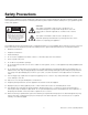
Safety Precautions Thank you for your purchase of this quality Runco video projector! It has been designed to provide you with the quality of video that is expected in a home theater. For the best performance, please read this manual carefully as it is your guide through the menus and operation. This symbol is intended to alert the user to the presence of important operating and maintenance (servicing) instructions in the literature accompanying the appliance.
1 Table of Contents TWO YEAR LIMITED WARRANTY ................................................................................. iii Safety Precautions ......................................................................................................... vi 1. Introduction ...............................................................................................................1 About This Manual .......................................................................................................
Table of Contents Installing the Projection Lens, Lamp and Cooling ........................................................24 Installing the Primary Lens ....................................................................................24 Installing the Lamp................................................................................................26 Liquid Cooling.......................................................................................................
Table of Contents Channel Setup......................................................................................................56 Auto Setup ...........................................................................................................58 Size and Position Menu .......................................................................................59 Image Settings Menu ...........................................................................................61 Working With the Lamp .....
Table of Contents 6. Serial Communications ..........................................................................................97 RS-232 Connection and Port Configuration ...............................................................97 Serial Command Syntax .............................................................................................97 7. Specifications ........................................................................................................103 SC-1 Specifications ....
1 List of Figures 2-1. SC-1 Top/Rear/Front/Side View (with Built-In Power Supply/Ballast) ............................5 2-2. SC-1 Input Panel..........................................................................................................7 2-3. SC-1 Control Panel ......................................................................................................9 2-4. DHD Controller Front Panel ........................................................................................11 Y 2-5.
List of Figures 3-27. Attaching the Anamorphic Lens to the Lens Ring .....................................................49 3-28. TheaterMaster Remote Control for SC-1 ..................................................................54 3-29. Channel Setup Menu................................................................................................56 3-30. Copying a Channel ...................................................................................................57 3-31.
1. Introduction This Owner’s Manual describes how to install, set up and operate the Runco Signature Cinema™ SC-1 DLP Projector and DHD Controller. It describes the features and functions available with DHD Controller Software version 2.0 and later. 1.1 About This Manual Y Throughout this manual, the Runco Signature Cinema™ SC-1 DLP Projector and DHD Controller are referred to collectively as the “SC-1.
Introduction Graphic Conventions: These symbols appear in numerous places throughout the manual, to emphasize points that you must keep in mind to avoid problems with your equipment or injury: Note NOTES emphasize text with unusual importance or special significance. They also provide supplemental information. Caution CAUTIONS alert users that a given action or omitted action can degrade performance or cause a malfunction.
Introduction When you select a Signature Cinema projector as the centerpiece of your home cinema, Runco becomes your partner in achieving the most extraordinary entertainment experience. As part of this personalized approach, Runco has engineered the SC-1 with a variety of setup tools allowing installation professionals to customize this projector for your unique home.
Introduction Key Features and Benefits ➤ The SC-1 offers these key features and benefits: • Native Resolution: 2048 x 1080 • Three-chip Digital Light Processing (DLP™) system • Two DVI Inputs (on DHD Controller) with High-bandwidth Digital Content Protection (HDCP) • HDTV Compatible • CinOptx™ Signature lens options for stunning sharpness and throw distance flexibility • Internal electromechanical shutter for quick picture mute and black stand-by Y • Inverse telecine deinterlacing of film-originated, st
2. Controls and Functions Figure 2-1 shows the key SC-1 components. The paragraphs that follow describe them. 3 Y 2 EL IM IN A R 1 4 5 6 7 8 9 PR 10 11 12 15 14 13 Figure 2-1. SC-1 Top/Rear/Front/Side View (with Built-In Power Supply/Ballast) Runco SC-1 Owner’s Operating Manual 5 2.
Controls and Functions 1. DOOR RELEASE To access SC-1 internal components, press this button to release the hinged door on the top of the projector. After closing the door, press the button again to latch it. 2. STATUS / CONTROL PANEL For a detailed description, refer to SC-1 Control Panel on page 9. 3. EXHAUST DUCT Connect the projector’s 8” top exhaust hole to a rigid duct.
Controls and Functions 2.2 SC-1 Input Panel Figure 2-2 shows the SC-1 rear input panel. EL IM IN A R Y 1 10 2 3 4 5 7 8 PR 6 11 9 Figure 2-2.
Controls and Functions 1. INPUT 1 (RGBHV) Five BNCs for connecting the RGBHV output from the DHD Controller. 2. INPUT 2 (DVI) HDCP-compliant digital video input. Connect the DVI output from the DHD Controller to this input. 3. INPUT 3 (Video) / INPUT 4 (S-Video) Not used. Connect all video sources to the DHD Controller. 4. ETHERNET Reserved for future use. Y 5. REMOTE Wired input from an external remote control or infrared receiver. EL IM IN A R 6. GPIO Not used. 7. RS422 Not used. 8.
Controls and Functions The SC-1 control panel includes an IR sensor, two-digit error code window, LCD status display and built-in keypad. The built-in keypad provides access to all software controls needed for working with the projector. (For more convenient functionality, use a remote control or serial commands via the DHD Controller.) Figure 2-3 shows the SC-1 control panel. 1 OSD On 59.94Hz 2 3 10 11 9 8 7 EL IM IN A R 12 Y Power On 44.96kHz 4 5 6 Figure 2-3. SC-1 Control Panel 1.
Controls and Functions 7. IR SENSOR Receives IR commands from the TheaterMaster remote control. 8. INPUT 2 (DVI) Press this button to select projector Input 2 (DVI output from the DHD Controller). 9. INPUT 1 (BNC) Press this button to select projector Input 1 (RGBHV output from the DHD Controller). 10. Menu Navigation Buttons: UP BUTTON ( ) Used to move the menu cursor up in the SC-1 menu system. EL IM IN A R Y LEFT BUTTON ( ) Used to move the menu cursor left in the SC-1 menu system.
Controls and Functions 2.4 DHD Controller Front Panel 1 2 EL IM IN A R Y Figure 2-4 shows the controls and indicators on the DHD Controller front panel; the paragraphs that follow describe them. 3 4 5 6 7 8 Figure 2-4. DHD Controller Front Panel 1. RUNCO ICON Lights red to indicate that the DHD Controller is in standby mode; lights blue to indicate that the unit is on. 2. POWER BUTTON Press once to toggle from standby mode to on mode. Press it again to return to standby mode.
Controls and Functions 7. ENTER BUTTON When an item is highlighted on the On-Screen Display, the ENTER button selects the item. 8. DOWN BUTTON Use to direct select aspect ratios or move the menu cursor down in the On-Screen Display. When no menu is present on-screen, this button toggles you through the different aspect ratios, in this order: Virtualwide 2.35 - Cinema - VirtualWide - Letterbox - Standard (4:3) - Anamorphic EL IM IN A R Y 9.
Controls and Functions 3. DVI 1 / DVI 2 (Digital) Two, HDCP-compliant digital video inputs for connecting a DVD player or HD tuner with a DVI or HDMI output. 4. HD1 / HD2 (5 x Analog BNCs) Two inputs (five BNCs per input) for connecting either RGB or component high-definition television signals. The DHD Controller automatically detects the signal format: RGB(HV) or YPrPb, 480p, 720p, 480i, 576i or 1080i. For best results, do not run your DVD player in progressive mode. EL IM IN A R Tip Y 5.
Controls and Functions 2.6 DHD Controller Remote Control Figure 2-6 shows the DHD Controller remote control, and the paragraphs that follow describe its functionality. 2 Y 1 3 EL IM IN A R 4 5 6 8 7 10 11 9 PR 12 13 Figure 2-6.
Controls and Functions 1. IR OUTPUT INDICATOR Lights when a button is pressed to indicate that an IR signal is being transmitted. 2. ON / OFF Press to turn the projector on or off. 3. ENTER Press to select a highlighted menu item or confirm a changed setting. 4. Cursor Buttons ( , , , ) Use these buttons to select items or settings, adjust settings or switch display patterns.
Controls and Functions 9. Aspect Ratio Selection Buttons Use the red buttons to select an aspect ratio directly or to enter numeric characters, as follows: ANA (Anamorphic) (3) For viewing 16:9 DVDs or HDTV programs in their native aspect ratio. 4X3 (Standard 4:3) (6) Scales the input signal to fit 4:3 display mode in the center of the screen. Y LETBOX (Letterbox) (9) For viewing LaserDisc movies or non-anamorphic DVDs on a 4:3 screen.
3. Installation 3.1 Remote Control EL IM IN A R Y To install batteries in the remote control, press up on the battery cover retainer clip and lift off the cover. Install the two AAA batteries with the correct polarity and then replace the cover. • Make sure that the battery polarities are correct when installing the batteries. Notes on Batteries • Do not mix an old battery with a new one or different types of batteries.
Installation 3.2 Quick Setup Table 3-1 gives a quick overview of the SC-1 installation process. The sections following this one provide detailed instructions. Note Installation should be performed by a qualified custom video installation specialist. Table 3-1. Installation Overview Choose a location for the projector 19 PR EL IM IN A R 1 For Details, Refer to page...
Installation Proper installation of your projector will ensure the quality of your display. Whether you are installing a projector temporarily or permanently, you should take the following into account to ensure your projector performs optimally. Choose the installation type that best suits your needs: front or rear screen. Table 3-2 compares these various installation methods. 3.
Installation Throw Distance ➤ Throw distance is the distance measured from the front of the projector to the screen. This is an important calculation in any projector installation as it determines whether or not you have enough room to install your projector with a desired screen size and if your image will be the right size for your screen. You can quickly estimate the throw distance by multiplying the width of the screen by the lens throw ratio; see Figure 3-1.
Installation Throw Distance Ranges: Table 3-3 lists the available lens options for the SC-1 and their associated throw ratios. Table 3-3. SC-1 Lens Options and Throw Ratios Lens Option (Note 2) Throw Ratio (Throw Dist. ÷ Screen Width) (Note 3) Throw Distance Range (in inches, with 100-inch Wide Screen) Minimum Maximum 1.78:1 screen 1.40-1.58 140 158 1.90:1 screen 1.32-1.50 132 150 1.78:1 screen 1.57-1.93 157 1.90:1 screen 1.48-1.81 148 181 1.96-2.55 196 255 1.84-2.40 184 240 2.
Installation Vertical and Horizontal ➤ Position Proper placement of the projector relative to the screen will yield a rectangular, perfectly-centered image that completely fills the screen. Ideally, the projector should be positioned perpendicular to the screen and in such a way that the lens center and screen center are aligned with each other, as shown in Figure 3-2. Screen Height Lens Center Lens Center Y x EL IM IN A R Projection Distance Floor Figure 3-2.
Installation Y 20% Offset EL IM IN A R Max. amount of image to one side of lens center = 20% (approx.) Note: This is a general example of lens shift. Projectors vary in their shift capabilities. No particular lens or projector is shown in this example. PR Figure 3-4. Horizontal Lens Shift (Example only) Vertical Lens Shift: The SC-1 provides up to 43% of vertical lens shift up or down. For example, with a 96 x 54-inch (16:9) screen, you can shift the image up to 23.22 inches (59.
Installation If you find that you cannot raise or lower the image enough using mechanical vertical offset, you may need to make keystone adjustments or vertically shift the image using the on-screen display (OSD) controls, to compensate. For detailed instructions, refer to Using the On-Screen Menus on page 67. If images remain keystoned or exhibit uneven brightness, the projector may simply be too high or low in relation to the screen. Relocate the projector to correct these issues.
Installation EL IM IN A R Y Serial Number Label PR Figure 3-5.
Installation Installing the Lamp ➤ To install the lamp, remove the screw holding the lamp/air filter cover in place. Then, lift the cover up and away from the projector. Turn the knob to open the inner lamp cooling compartment and reveal the cathode end (–) of the lamp; see Figure 3-6. WARNING Xenon arc lamps are under high pressure and must be handled with great care at all times. Lamps may explode if dropped or mishandled.
Installation EL IM IN A R Y Before installing the projector lamp, check the lamp cradle (anode end) location and adjust as necessary; see Figure 3-7. For a 2.0-kW lamp, move the cradle to the rear position, approximately 1” closer to the reflector. Figure 3-7. Lamp Cradle Adjustment PR To complete the lamp installation, refer to Lamp and Filter Replacement on page 87 for detailed instructions. Observe all warnings, and wear protective clothing and shielding.
Installation Installing the Extractor ➤ Fan and Exhaust Duct Install an extractor fan and duct to pull warm exhaust air from the projector at a minimum rate of 600 cubic feet per minute (CFM). WARNING Do not operate the projector without an extractor fan installed! Y If necessary, consult a knowledgeable HVAC technician for help with designing and installing a cooling solution that best suits your site and installation requirements.
Installation ” . 10 EL IM IN A R Y Min Figure 3-8. Extractor Fan Configurations If you are installing a SC-1 with the optional CineWide with AutoScope system, proceed as follows to install the anamorphic lens mounting assembly (AutoScope lens motor). Note 3.5 Installing the Optional CineWide Lens Mount Do not install the CineWide lens yet, only the lens motor. You will install the CineWide lens after you install the projector and adjust the primary lens.
Installation Use the supplied hardware to attach the lens motor extension bracket to the top of the lens motor as shown in Figure 3-10. EL IM IN A R Y Attach Extension Bracket ➤ to Lens Motor Figure 3-10. AutoScope Lens Motor with Extension Bracket Install Anamorphic Lens ➤ Motor PR Note The anamorphic lens mounting kit is partially pre-assembled at the factory – the AutoScope lens motor and lens mounting assemblies are both fully assembled.
Installation Mount the SC-1 on a strong supporting structure or cart. Carts can be useful when moving a projector during a presentation or from site to site. If possible, lock the wheels when it’s in position to prevent it from being moved during a presentation. 3.6 Mounting the SC-1 Take special care if using a mobile cart; avoid sudden stops, force and uneven surfaces that may cause the top-heavy cart to lurch and overturn.
Installation 3.7 Connections to the SC-1 and DHD Controller Proceed as follows to connect the DHD Controller to the SC-1, your video sources, external controller(s) – if present – and AC power. When connecting your equipment: • Turn off all equipment before making any connections. • Use the correct signal cables for each source. To access the SC-1 input panel, remove the two screws holding the input panel cover in place.
PR EL IM IN A R Y SC-1 Input Panel Red Green Blue Horiz Vert Installation RGB-HV OUT SYSTEM CONTROL INTERFACE INPUTS Serial No Pr R Y G Pb B V 2 1 Y G CAUTION: TO REDUCE THE RISK OF ELECTRIC HD1 3 IR SHOCK, DO NOT REMOVE COVER. NO USERSERVICEABLE PARTS INSIDE. REFER SERVICING TO QUALIFIED SERVICE CENTER.
Installation Connecting Source ➤ Components to the DHD Controller Connect your video sources to the DHD Controller as shown and described in the sections that follow. DVI Connections: See Figure 3-14. Use the DVI inputs whenever possible. This ensures the highest video quality because the signal is carried in the digital domain throughout the entire signal path, from source component output into the projector. Tip You can also connect computers with DVI output to these inputs.
Installation Digital (DTV) RGB or Component Video Connections: See Figure 3-15. R/Pr G/Y INPUTS B/Pb H V TRIGGERS HD1 1 2 3 HD2 R/Pr G/Y B/Pb H V Pb DVI 2 Pr Y Component Video Video S-Video 2 EL IM IN A R DVI 1 Y S-Video 1 Horiz Vert PR Red/Pr Green/Y Blue/Pb DTV or Progressive Component (YPbPr) Source Figure 3-15.
Installation Analog (Computer) RGB Connections: See Figure 3-16. R/Pr G/Y INPUTS B/Pb H V TRIGGERS HD1 1 2 3 HD2 G/Y R/Pr B/Pb H V S-Video 1 Pb DVI 2 Y Pr Component Video Video S-Video 2 EL IM IN A R Y DVI 1 PR Red Green Blue Horiz Vert Personal Computer Figure 3-16.
Installation Composite/S-Video/Component Video Connections: See Figure 3-17. R/Pr G/Y INPUTS B/Pb H V TRIGGERS HD1 1 2 3 HD2 R/Pr G/Y B/Pb H V S-Video 1 DVI 2 Pb Y Pr Component Video Video S-Video 2 EL IM IN A R Y DVI 1 Pr Y PR Pb DVD Player, VCR, Satellite Receiver, Laser Disc etc. Figure 3-17.
Installation RS-232 Controller ➤ Connection Use a standard, 9-pin RS-232 cable to connect a PC or home theater control/automation system (if present) to the RS-232 Control port on the DHD Controller; see Figure 3-18. For more information about using this connection, refer to Serial Communications on page 97.
Installation The SC-1 is optionally available in a split-body configuration in which the power supply/ballast is separate from the projection head. This configuration is useful for installations where the projection area is too small to accommodate a single-body SC-1, or the 220-VAC source cannot be conveniently accessed from the projection area. Note If the power supply/ballast is internal to your SC-1 (as shown in Figure 2-1), continue with the next step, Connecting to AC Power.
Installation Connecting the Ballast to the Lamp Igniter: The external power supply/ballast connects to the lamp igniter via two, high-voltage DC power cables with “twist-lock” connectors. The connectors are color-coded and of different genders for easy identification (red=positive; black=negative); see Figure 3-21. To connect the external power supply/ballast to the igniter: 1. Connect the positive (red, male) DC power connector to the red (female) terminal on the lamp igniter connection panel.
Installation Connecting the Ballast to the AC/Lamp Control Input Panel: Connect the AC power, lamp ballast control cable and lamp ballast safety interlock cable to the AC/lamp control input panel as shown in Figure 3-22. Projector Status (for future use) EL IM IN A R AC Voltmeter Y FROM BALLAST Control (male) PR Interlock (female) FROM BALLAST Figure 3-22.
Installation Connecting to AC Power ➤ The SC-1 system includes two (2) AC power cords (one each for the DHD Controller and projector). DHD Controller: Plug the female end of one power cord into the AC receptacle on the rear of the DHD Controller. Connect the other end to your AC power source (100 to 240 VAC). Projector: Similarly connect the SC-1 to a nearby AC outlet. The input voltage must be between 200 and 240 VAC. The SC-1 requires a dedicated, 220-VAC/30A circuit.
Installation Before powering up the projector and igniting the lamp, you must define in memory which size lamp is installed, otherwise you risk severely over-driving or under-driving a lamp. WARNING Explosion hazard. DO NOT turn the projector on until you have defined the lamp size. EL IM IN A R Y 1. Press MENU. The Status Display at the top of the projector will show a “Lamp Size” of 2000, 3000, 4500 or 6000 watts. See Figure 3-23.
Installation Power-Up Sequence ➤ 1. Turn on your source components. 2. Turn on the main power switch at the rear of the DHD Controller. 3. If this is an AutoScope-equipped projector, turn on the main power switch at the rear of the AutoScope lens motor. The lens motor power switch is located next to the AC input (see Figure 3-19). 4. Press the ON button on the remote control – or the POWER button on the DHD Controller front panel – to turn on the system.
Installation Upon powering up the projector with a newly installed/replaced lamp, use the LampLOC feature of the SC-1 to adjust the lamp position to help ensure optimized operation as well as peak brightness at the screen. You do not need to display an image on-screen to do this; however, the lamp must be on and the shutter open. To perform the LampLOC adjustment: 1. Press MENU on the built-in keypad or TheaterMaster remote control to display the Main Menu. 2. Select Lamp from the Main menu.
Installation 3.10 Selecting the Input Source By default, the SC-1 is configured to display the signal received on Input 1 (RGB). To use Input 2 (DVI) instead: 1. On the DHD Controller, press MENU and enter the Service Menu passcode. Note You must enter a passcode to access the Service menu. 2. Select Service from the Main Menu. 3.11 Adjusting the Picture Orientation to select DVI/HDMI, then press ENTER. EL IM IN A R 4. Press Y 3. Select Display Device from the Service Menu.
Installation To focus the projected image: Focus 1. Display a good test pattern appropriate for analyzing image focus and geometry, such as a single crosshair centered across the image. EL IM IN A R With the projector in its permanent location, turn the lens zoom ring on the primary lens to enlarge or shrink the image in each direction as necessary. Y 2. Rotate the knob as needed to produce a tightly-focused image. Using a 4.
Installation 3.13 Installing and Adjusting the CineWide Anamorphic Lens If you are installing a CineWide-equipped projector, proceed as follows to install and adjust the anamorphic lens. Note It is extremely important that the primary lens is properly adjusted before you install the anamorphic lens. Ensure that the image from the primary lens is perfectly centered on the screen. Y The Anamorphic lens mount kit consists of everything shown in Figure 3-26.
Installation LENS THREADS INTO RING FO CU S PR EL IM IN A R Y 4. Attach the Lens Adapter Ring to the Pitch Adjustment Yoke using the three screws provided for this purpose; see Figure 3-27. Then, attach the lens to the Lens Adapter Ring by threading it clockwise. Figure 3-27.
Installation Configure Lens Motor ➤ Trigger CineWide with AutoScope maintains constant image height independent of the aspect ratio, while using the full display resolution of the projector. It accomplishes this by moving the anamorphic lens in front of the primary lens when widescreen material is being viewed. When the viewer transitions back to 16:9 or 4:3 source material, the anamorphic lens moves out of the light path.
Installation Height (Y) Adjustment: With the white field still on-screen, loosen the Height/Y Adjustment T-Screws on either side of the lens. Then, slowly move the anamorphic lens into place so that there are no shadows on the top or bottom of the screen: EL IM IN A R Y Too Low Correct position Too High When the height is properly set, tighten the Height Adjustment T-Screws to secure the lens in place. PR Pitch (Angle): Next, angle the lens to even out any top-to-bottom pincushion distortion.
Installation EL IM IN A R Y Yaw Adjust: Loosen the Yaw/X-Adjustment Levers to allow the lens to pivot freely from side to side. Then, angle the lens to even out any left-right pincushion distortion: Correct Position Wrong Position Once the proper lens angle has been set, firmly tighten the Yaw/X-Adjustment Levers to secure the lens in place. Geometry: 2. Loosen the three Lens Rotation Set Screws (shown in Figure 3-27) on the lens adapter plate just enough to allow it to rotate freely. 3.
Installation After you have installed and adjusted the projector and lens (or lenses), you are ready to begin calibrating the RGBHV input (Input 1) to the SC-1. Note Runco calibrates both the SC-1 and DHD Controller at the factory for optimum performance in most typical home cinema environments, before the system ships. Y Carefully assess the displayed image quality before proceeding with calibration.
Installation SYSTEM 1 MAIN 2 FUNCS 3 4 Y SOURC EL IM IN A R 11 + PREV CH - 12 + - GUIDE 5 MENU 6 7 8 13 PR EXIT 14 INFO 9 10 DIS Figure 3-28.
Installation 1. POWER Button Hold this button down for 1-2 seconds to turn on or off the projector. TheaterMaster Remote Control Functions 2. FUNCS Button This button brings you to a sub-page in which you can access the projector’s internal test patterns, view help text, auto-calibrate the projector and perform various other functions. 3. BACKLIGHT Button Lights the LCD display and buttons for use in a dark room. 4. LCD Display Displays currently-selected LCD Menu page. Y 5.
Installation Navigating the Projector ➤ Menus To select a sub-menu using the remote keypad, do one of the following: • Press the number key corresponding to the function menu you wish to access, such as 2 for the Image Settings menu. • Press or on the directional keypad to highlight the desired option, then press ENTER or . Y The corresponding function menu or pull-down list of further options will then appear.
Installation To display the Channel Setup menu, press 3 or highlight Channel Setup and press ENTER or . The Channel Setup menu appears with the active channel highlighted. WHAT APPEARS IN THE CHANNEL SETUP MENU? This menu lists all channels defined so far and indicates where they are connected on the input panel. Y The far left column lists channel numbers currently defined.
Installation Auto Setup ➤ Use the Auto Setup feature of the SC-1 as a convenient starting point for calibrating the projector inputs for optimum picture quality. Note You cannot use Auto Setup with a locked channel. Copy the locked, factory-default channel for the current input to a new channel before using Auto Setup; refer to Copying Channels on page 57.
Installation In the Size and Position Menu, you can increase or decrease the size of your image, change its proportion (aspect ratio), move the image to a specific area of the screen, and refine other related parameters. Use Size and Position controls to match the image precisely to the screen. Changes made in the Size and Position menu take effect immediately and are saved when you exit the menu.
Installation • Full Size: Select Full Size to use all pixels for displaying the image, regardless of source or original aspect ratio. Incoming source material having a different aspect ratio than the projector will be stretched to fill the display. • Full Width: Select Full Width to fill the projector’s display from left-to-right without changing the original aspect ratio of the image.
Installation Note The values shown represent where the approximate center of the image lies in relation to the total number of pixels available horizontally or vertically. This varies widely according to the signal; watch the image while adjusting. Use options in the Image Settings menu to alter your image without affecting its size or position. Changes made in this menu are applied immediately and saved when you exit the menu.
Installation Video Options: This sub-menu is not applicable to the SC-1. Input Levels (Input 1 only): Good RGB or input levels — that is, the drives and black levels for each of the three primary colors, red, green and blue — ensure that images from analog sources other than decoded video have maximum contrast without crushing black or white.
Installation • Black Levels and Drives: To check your image and adjust these controls: 1. Make sure overall “Contrast” and “Brightness” settings are both set to near 50. (Not required for “Auto Input Level” adjustment.) 2. Check the color temperature setup using an internal grayscale test pattern, making sure to obtain a neutral grayscale. (Not required for “Auto” adjustment.) 3. If the blacks and/or whites appear OK, input levels do not need adjustment.
Installation 3.15 Working With the Lamp Access the Lamp menu to: • Choose a lamp mode for regulating power and light output. • View information pertaining to past and present lamps. • Record the lamp serial number in the projector’s memory. Lamp Hours (read-only): Lamp Hours shows the number of hours logged on the current lamp. Whenever you record a new lamp serial number, the SC-1 automatically resets this value to “0” and begins to log time for the new lamp.
Installation Lamp Mode: Select the Lamp Mode you want to use in order to control the light output. You can choose to run the lamp as bright as possible, you can power the lamp with a specific wattage appropriate for the installed lamp or you can set a specific intensity (brightness) to maintain. Keep in mind that higher lamp power settings can shorten lamp life.
Installation HOW LONG CAN I MAINTAIN BRIGHTNESS? The SC-1 can maintain your “Intensity” setting until the required power reaches the maximum rating for the lamp. The lower the setting, the longer it will take to reach this threshold and the longer you can maintain the desired brightness. Keep in mind that once the lamp power reaches its maximum wattage (see “Power,” above), this tracking is no longer possible.
4. Operation Press the MENU button on either the remote control or the DHD Controller front panel to display the Main Menu. Y To select a menu item, use the and buttons on either the remote control or the DHD Controller front panel to highlight it. Press ENTER to confirm your selection. PR EL IM IN A R The SC-1 OSD menus are arranged hierarchically, as shown in Figure 4-1. Depending on the selected input source and signal characteristics, some menu options may not be available.
Operation Picture Input Position ISF Presets Information (read-only) PR Test Video ISF Night - Input Image ISF Night - Input Color ISF Day - Display Color ISF Day - Input Image Note: Virtualwide 2.35 is available only on SC-1 projectors equipped with the CineWide option (secondary anamorphic lens).
Operation The Main Menu is the starting point for accessing all projector functions. Main Menu (The Calibration and Service menus are hidden and not accessible until you enter a passcode.) Runco Video Input Source Aspect Ratio Picture Input Position ISF Presets Information Calibration EL IM IN A R Y Service From the Main Menu, select Input Source to choose a video signal source. The active source is indicated by an arrow (>) to its left; in the example at left, Composite is the active source.
Operation Table 4-1. Aspect Ratio Settings Aspect Ratio Remote Control Key Anamorphic ANA Description EL IM IN A R Y 16:9 Image on 16:9 Screen Select Anamorphic to view 16:9 DVDs and HDTV programs in their native aspect ratio. 4:3 images are stretched horizontally to fit a 16:9 screen. 4:3 Image on 16:9 Screen Standard 4:3 4X3 Active Image Area (4:3) Letterbox LET BOX PR Letterbox Image on 16:9 Screen Standard 4:3 scales the input signal to fit in the center of the 16:9 screen.
Operation Table 4-1. Aspect Ratio Settings (continued) Remote Control Key Virtualwide 2.35 SVC Description 2.35:1 Image on 16:9 Screen Virtualwide 2.35 is available only on SC-1 projectors equipped with the CineWide option. EL IM IN A R 2.35:1 Image on 16:9 Screen with VirtualWide 2.35 A 2.35 image is stretched anamorphically in both directions to fill a 16:9 image. (The secondary anamorphic lens then “stretches” the image back to 2.35:1.) Y Aspect Ratio 2.35:1 Image on 2.
Operation Although it may be possible to obtain satisfactory picture quality using the naked eye and regular program material, Runco recommends using the following calibration tools for best results: • External test pattern source – Ovation Multimedia, Digital Video Essentials or AVIA test DVD or equivalent. • A blue filter (provided with many test DVDs), for color level and tint adjustments. Connect your test pattern source to the input that you are calibrating and proceed as follows.
Operation EL IM IN A R Y Contrast: On your external test pattern source, select a stepped, gray-bar pattern like the one shown in Figure 4-3. Figure 4-3. Typical Gray Bar Pattern for Adjusting Contrast Select Contrast and press ENTER. Adjust the contrast to a point just below which the white rectangle starts to increase in size. Brightness and contrast controls are interactive. A change to one may require a subtle change to the other in order to achieve the optimum setting.
Operation blue red EL IM IN A R Y magenta green cyan yellow gray Select Color and press ENTER. While looking at the color bar pattern through a blue filter, adjust the color saturation level until the outermost (gray and blue) color bars appear to be a single shade of blue: Tint: Tint or “hue” is essentially the ratio of red to green in the color portion of the image. When tint is decreased, the image appears redder; when it is increased the image appears greener.
Operation EL IM IN A R Y Sharpness: “Sharpness” is the amount of high-frequency detail in the image. To adjust sharpness, select Sharpness from the Picture menu and press ENTER. On your external test pattern source, select a pattern like the one shown in Figure 4-5. Adjust as needed, looking for white edges around the transitions from black to gray and differently-sized lines in the “sweep” patterns at the top and bottom. Lower the sharpness setting to eliminate them. Figure 4-5.
Operation Overscan: Image Overscan pushes the outside edge of the active picture area of the video signal out beyond the edge of the display area. Some television programs are produced based on the assumption that older television sets may not display the outer edges of the broadcast picture area. Over scan effectively trims away these inactive, outer edges and enlarges the remaining portion of the image to fill the display area. Select from 1% to 10% of Overscan, as desired.
Operation Use the Calibration menu to perform advanced picture quality adjustments. This menu should be used by ISF-certified technicians only. Calibration Calibration Note You must enter a passcode to access the Calibration menu. ISF Night Display Color Input Image Input Color To recall the ISF Night or ISF Day settings, select “ISF Night” or “ISF Day” from the ISF Presets menu (see above). Y ISF Night - Display Color: Use the Display Color settings to adjust the projector lamp intensity.
Operation ISF Day - Input Image: Refer to ISF Night - Input Image. ISF Day - Input Color: Refer to ISF Night - Input Color. Save ISF Settings: Whenever you make a change to the ISF settings, you should always save it. Select Save ISF Settings from the ISF Calibration menu to do this. In the event you ever have to perform a System Reset, you can restore the saved ISF settings by selecting Restore Saved Settings in the Service menu. (System Reset and Restore Saved Settings are described on page 82.
Operation Use the Service menu to access advanced projector configuration settings. This menu should be used by ISF-certified technicians only. Service Service Note You must enter a passcode to access the Service menu. Test Video Input Names Remote Control Analog Out Mode Test Video: Select Test Video from the Service Menu to access the internal test patterns on the SC-1. Four patterns are available, consisting of white/gray or colored bars. Display Device Press MENU to exit test pattern mode.
Operation Tip Note Use the DHD Controller front-panel keypad to change its IR code. Then, change the code sent by the remote to match as described below. Do not change the “Type” setting in this menu. When you change a remote code on the DHD Controller, you must re-program your remote control to send that same code. To do this: EL IM IN A R Y 1.
Operation • Configure: Select Configure from the Display Device menu to change the picture orientation, correct a “keystoned” (trapezoidal) image, access the lamp timer, perform lens adjustments and quickly optimize various display settings. • Installation - Orientation: Refer to Adjusting the Picture Orientation on page 46. • Installation - Keystone: If the projector and screen are not installed perpendicular to each other, the image may become distorted in a trapezoidal shape, as shown in Figure 4-6.
Operation Tip To configure a trigger to activate when the system is turned on – for example, when using the trigger to control a retractable screen – assign that trigger to all aspect ratios. To save the trigger settings so that they can be restored after a System Reset (described below), press repeatedly to highlight “Save.” Then, press ENTER.
5. Maintenance and Troubleshooting The SC-1 is designed for safe and reliable operation. However, safe operation is not assured by design alone; installers, service technicians, trained operators and all other users must maintain a safe environment at all times. Please read and understand all warnings and precautions in this manual and on the projector itself before attempting to operate or service the projector. Y Never look directly into the projector lens or at the lamp.
Maintenance and Troubleshooting 5.2 Maintaining Proper Cooling The high-intensity lamp and electronics rely on a variety of cooling components to reduce internal operating temperatures. Regular checking and maintenance of the entire cooling system is critical to prevent overheating and sudden projector failure, and helps to ensure reliable operation of all projector components over time.
Maintenance and Troubleshooting Note If the exhaust duct becomes significantly blocked — or if a fan fails — the projector’s airflow sensor should trigger a shutdown before the projector becomes overheated or unsafe. Regardless, check the airflow periodically. To help ensure optimized performance and reliability, check electrical, optical and other components regularly as described below. Y SHOCK HAZARD. Turn off the SC-1 and disconnect it from AC before performing any maintenance or cleaning.
Maintenance and Troubleshooting Cleaning the Lens ➤ Removing Dust: 1. Brush most of the dust off with a camel-hair brush and/or blow dust away with compressed air. 2. Fold a microfibre cloth smooth and gently wipe remaining dust particles off the lens. Make sure to wipe evenly with the smooth portion of the cloth that has no folds or creases. Do not apply pressure with your fingers — use the tension in the folded cloth itself to collect the dust. 3.
Maintenance and Troubleshooting Air Flow Interlocks: The lamp fan vane switch is located within the lamp cooling compartment. The extractor vane switch is located just inside the top exhaust duct on the projector. Check and, if necessary, clean the switches to remove accumulated dust or dirt that could impede movement. Within the exhaust duct connected at the top of the projector, adequate airflow must be maintained and routed away from the operating area surrounding the projector.
Maintenance and Troubleshooting 5. Using a hex wrench of the appropriate size, loosen the set screws from the negative/cathode (rear, 7/64”) and positive/anode (front, 3/16”) lamp connectors; see Figure 5-1. Apply minimal torque and DO NOT stress the quartz tube. EL IM IN A R Y Remove anode connector Remove cathode connector (inside lamp cooling compartment) Figure 5-1. Disconnecting the Old Lamp PR 6. Carefully slip the positive anode connector off the front of the lamp. 7.
EL IM IN A R Y Maintenance and Troubleshooting Figure 5-2. Installing A New Lamp 12. Rest the anode (+) end of the lamp on the lamp cradle as shown in Figure 5-2. Then, slip the positive lamp connector over the bulb end. PR 13. Tighten the set screws in both negative and positive lamp connectors; see Figure 5-3. If you accidentally touch the quartz body of the lamp with your bare hands, clean the surface as described in Maintenance and Cleaning on page 85. Figure 5-3.
Maintenance and Troubleshooting 14. Check Leads: Make sure that the anode (+) lead between lamp and igniter is well away from any projector metal such as the reflector or firewall. Leads too close to metal parts will cause arcing during starting WARNING pulse. This is a SAFETY HAZARD, and the lamp may not ignite. 15. Close the inner lamp cooling compartment door and turn the knob clockwise to secure it. 16. Replace the lamp/air filter cover and tighten the screw to secure it. 17.
Maintenance and Troubleshooting Note Always record the serial number of a new lamp. Do this only if you have just installed a new lamp. This will ensure that the lamp timer is not reset on an old lamp and that the number of hours logged on the lamp is accurate. Whenever you replace the lamp – or more often if the projector is installed in an extremely dusty environment – you should also replace the air filter. The filter is located on the lamp side of the projection head, near the front (see Figure 2-1).
Maintenance and Troubleshooting 5.6 Troubleshooting Tips Table 5-1 provides some general guidelines for troubleshooting problems you may encounter with the SC-1. If the suggested solutions fail to resolve the problem or if you encounter an issue not described here, please contact Runco Technical Support. Table 5-1. Troubleshooting Chart Symptom Solution • The SC-1 is not plugged in or the AC outlet is not active. • The DHD Controller is not plugged in or the AC outlet is not active.
Maintenance and Troubleshooting Table 5-1. Troubleshooting Chart (continued) Symptom Possible Cause(s) Solution • DVD player is connected to the Component input and set to progressive scan mode. • Turn off progressive scan on the DVD player. Or, connect the DVD player to the HD1 or HD2 input. Image appears “squeezed” or vertically stretched into center of screen. • Incorrect aspect ratio selection. • Select a different aspect ratio. The display is jittery or unstable.
Maintenance and Troubleshooting Error Codes ➤ If the status code display on the back of the projector shows one of the following values, you have encountered a likely system error requiring the attention of a qualified service technician. Acknowledge and clear the error by pressing EXIT twice on the rear-panel keypad. Try resetting the projector by powering it off, allowing it to cool and powering it on again. Refer to Table 5-2 and contact your dealer if the problem persists.
Maintenance and Troubleshooting Table 5-2. SC-1 Error Codes (continued) Code Description Power and Cooling Lamp has shut down due to fan failure. 46 Red DMD heat sink overheated. 47 Green DMD heat sink overheated. 48 Blue DMD heat sink overheated. 49 Prism overheated. 4C Projector shutdown due to critical error. 4D Integrator has overheated. 4E Inadequate lamp air intake rate (interlock) 4F Inadequate air exhaust rate (interlock) 53 Fan 3 has failed (side [rear] intake fan).
Maintenance and Troubleshooting Table 5-2. SC-1 Error Codes (continued) Code Description Panel Driver and Formatter Unrecognized IRAM (panel driver). 81 Unable to program device on IRAM. 82 TI flash download failure. 83 TI flash download fault; partial success. 84 TI flash download fault; partial success. 85 TI-I2C write failure. EL IM IN A R Y 80 87 Consecutive faults from modular Formatters. 90 Red modular Formatter communication failure.
6. Serial Communications To interface the DHD Controller with a home theater automation/control system or a PC running terminal emulation software, connect it to your control system or PC as shown in Figure 3-18. 6.1 RS-232 Connection and Port Configuration Serial commands to the DHD Controller take the following form: EL IM IN A R • Commands are not case-sensitive. Y Configure the RS-232 controller or PC serial port as follows: no parity, 8 data bits, 1 stop bit and no flow control.
Serial Communications Table 6-1 lists the RS-232 command set. The “Parameter (min/max)” column shows the valid parameter ranges, or “NA” for commands that take no parameters. When you enter a valid command, the DHD Controller executes it and acknowledges it with a plus sign on the command line (+ >). When you enter an invalid command – one that is misspelled or followed by values outside the valid range for that command – the DHD Controller ignores it and returns a minus sign (- >). Table 6-1.
Serial Communications Table 6-1. Serial Commands (continued) Command Parameter (min/max) Value Stored? Description Aspect Ratio Commands NA YES Selects the Anamorphic aspect ratio ASPECT? NA NA Returns current aspect ratio ASPECTIN? NA NA Returns the input source aspect ratio ASPECTOUT? NA NA Returns output screen size CINEMA NA YES Selects the Cinema aspect ratio LETTERBOX NA YES Selects the Letterbox aspect ratio OUT169 NA YES Sets the output screen to 1.
Serial Communications Table 6-1.
Serial Communications Table 6-1.
Serial Communications PR EL IM IN A R Y Notes: 102 Runco SC-1 Owner’s Operating Manual
7. Specifications 7.1 SC-1 Specifications Table 7-1 lists the SC-1 specifications. Table 7-1. SC-1 Specifications Digital Light Processing (DLP), 3-chip, SuperOnyx DMD Native Resolution: 2048 x 1080 (1.90 native aspect ratio) Aspect Ratios: Refer to Table 7-2 Video Standards: Refer to Table 7-2 Scan Frequency: EL IM IN A R DTV Compatibility: Y Projector Type: 480p, 720p, 1080i Horizontal: 15 kHz to 120 kHz Vertical: 23.
Specifications Table 7-1. SC-1 Specifications (continued) Brightness and Contrast: Cinema Standards Measurement System (CSMS) Specifications Brightness (with 2.0-kW lamp): 331.0 foot-Lamberts (fL) Contrast Ratio (with 2.0-kW lamp): 243:1 - 485:1 EL IM IN A R Y These measurements are taken from the projector in a controlled, home theater environment. All measurements are made to ANSI/NAPM IT7.
Specifications 7.2 DHD Controller Specifications Table 7-2 lists the DHD Controller specifications. Table 7-2. DHD Controller Specifications 4:3, Letterbox, 16:9 Anamorphic, VirtualWide, Cinema, VirtualWide 2.
Specifications 7.3 SC-1 Dimensions Figure 7-1 and Figure 7-2 show the SC-1 dimensions (all dimensions are in inches). 58.037 25.750 EL IM IN A R 0 0 Y 29.638 17.355 9.042 0 9.862 22.875 0 2.875 0 3.612 6.013 7.875 7.138 0 19.925 25.100 27.450 48.712 0 0 0 2.875 15.450 18.052 21.552 Ø .625 PR 39.950 Figure 7-1.
Specifications 49.446 29.638 25.750 0 0 0 9.862 22.875 0 EL IM IN A R 0 2.875 0 3.612 6.013 7.875 7.138 0 19.925 25.100 27.450 0 0 2.875 15.450 18.052 21.552 Ø .625 39.950 PR Figure 7-2. SC-1 Dimensions (without Built-In Power Supply/Lamp Ballast) Runco SC-1 Owner’s Operating Manual 107 48.712 Y 17.355 9.
Specifications PR EL IM IN A R Y Notes: 108 Runco SC-1 Owner’s Operating Manual
SERIAL NUM BER RUMA-011105 rev 07-28-06 v2.1 Runco International • 2900 Faber Street • Union City, CA 94587 • Ph (510) 324-7777 / (800) 23RUNCO / Fax (510) 324-9300 www.runco.