
Installation guide


Configuration Scenarios
Runco WindowWall Installation Guide 107
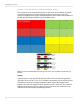
In the diagrams that follow, a darkened bar over a settings means that setting is not
necessary for this scenario and it doesn’t matter to what it is set.
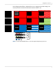
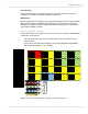
Note: 3 x 3 Runco WindowWall with 2 x 2 sub wall, upper left displaying source A1.
A1
Switch 1 Loop
Switch 2 Loop
Switch 3
Digital
Switch 4 Loop
Internal Loop Digital 1
X External Loop Digital 1
Use Loop External
A2
Wall Width 2
Wall Height 2
Unit Row 1
Unit Column 2
X Wall Mode
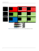
B1
Wall Width 2
Wall Height 2
Unit Row 2
Unit Column 1
X Wall Mode
B2
Wall Width 2
Wall Height 2
Unit Row 2
Unit Column 2
X Wall Mode
A3
Wall Width 2
Wall Height 2
Unit Row 1
Unit Column 1
O Wall Mode
B3
Wall Width 2
Wall Height 2
Unit Row 1
Unit Column 1
O Wall Mode
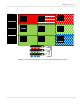
C1
Wall Width 2
Wall Height 2
Unit Row 1
Unit Column 1
O Wall Mode
Switch 1 Digital 1
Switch 2 Digital 2
Switch 3 Digital 3
Switch 4 Digital 4
Internal Loop Digital 1
X External Loop Dual Link In
Use Loop External
C2
Wall Width 2
Wall Height 2
Unit Row 1
Unit Column 1
O Wall Mode
C3
Wall Width 2
Wall Height 2
Unit Row
1
Unit Column
1
O Wall Mode
Switch 1 Loop
Switch 2 Loop
Switch 3 Digital 3
Switch 4 Digital 4
Internal Loop Digital 1
X External Loop Dual Link In
Use Loop External
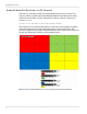
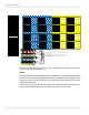
Source 1 Source 2 Source 3
Source 9
Source 4 Source 5 Source 6
Source 7 Source 8
A
Loop Out
Dual Link In
Loop Out
Dual Link In
Loop Out
Dual Link In
Quad Module Route C
Quad Module Route B
Quad Module Route A
Digital 1 Digital 2 Digital 3 Digital 4
B
Digital 1 Digital 2 Digital 3 Digital 4
Digital 1 Digital 2 Digital 3 Digital 4
C
2
2
Unit Row 1
Unit Column 1
X Wall Mode
Wall Width
Wall Height
3