Model :RFBW01011 Model :RFBE 01011 Model :RFBG 01011 Etagere Operators’ Manual Manual de Operadora de Etagere Inspect product prior to installation. Contact info@runfinegroups.com prior to returning product to retailer. Inspeccione el producto antes de su instalación. Póngase en contacto con info@runfinegroups.com antes de devolver el producto al vendedor.
PARTS LIST A. B. C. D. E. F. G. H. I. J. K. L. M. N. O. P. / Lista de componentes TOP LEFT SIDE PANEL TOP RIGHT SIDE PANEL TOP PANEL BOTTOM PANEL FIXED SHELF PANEL BACK TOP CROSS BAR ADJUSTABLE SHELF PANEL LOWER LEFT SIDE PANEL LOWER RIGHT SIDE PANEL LOWER BACK TOP CROSS BAR LOWEST BACK CROSS BAR FRONT DECORATIVE PANEL LEFT DOOR PANEL RIGHT DOOR PANEL DOWN OPENING DOOR PANEL BACK PANEL A. PANEL LATERAL IZQUIERDA SUPERIOR B. PANEL LATERAL DERECHO SUPERIOR C. PANEL SUPERIOR D. PANEL INFERIOR E.
HARDWARES 1. DOOR KNOB 2. DOOR KNOB SCREW 3. CAM LOCK NUT & BOLT 4. WOOD DOWEL 5. SHELF SUPPORTS 6. DOOR MAGNET AND SCREW 7. WOOD SCREW (12MM L) 8. DOOR HINGES & SCREW 9. PLASTIC ANCHOR & SCREW 10. CHAIN 3PCS 3PCS 25SETS 26PCS 4PCS 3SETS 25PCS 6SETS 2SETS 2SETS 1. PUERTA PERILLA 2. TORNILLO DE LA PUERTA PERILLA 3. CONTRATUERCA & PERNO CAM 4. ESPIGA MADERA 5. SOPORTA DE ESTANTE 6. IMÁN Y TORNILLO DE LA PUERTA BLANCA 7. TORNILLO DE MADERA (12MM L) 8. BISAGRAS & TORNILLO 9. ANCLA DE PLÁSTICO & TORNILLO 10.
TOOLS REQUIRED (NOT INCLUDED) / HERRAMIENTAS REQUERIDAS (NO INCLUIDO) Destornillador de cabeza plana FLAT HEAD SCREWDRIVER PHILLIPS SCREWDRIVER DESTORNILLADOR PHILLIPS Por favor, lea las instrucciones antes del montaje. Please read instructions before assembly. Perform assembly on a carpeted surface to prevent scratching. Realizar el montaje sobre una superficie enmoquetada para evitar que se raye. This assembly process require at least two people.
ASSEMBLE TOP SIDE PANELS,FIXED SHELF & BACK TOP CROSS BAR (STEP 1)- #B ARMAR LOS PANELES DE LATERALES SUPERIORES, ESTANTE FIJO Y BARRA TRANSCERSAL SUPERIOR TRASERA. (PASO 1) -- # B Insert wood dowels (4) into the pre-drilled hole of fixed shelf panel (E) & back top cross bar (F), attach fixed shelf panel (E) and back top cross bar (F) to top side panel (A) & (B) as shown (Figure 3).
ASSEMBLE TOP PANEL, BOTTOM PANEL AND DOOR MAGNETS(STEP 2) ARMAR LOS PANELES DE LA PARTE SUPERIORES, PANEL INFERIOR Y IMAN DE LA PUERTA (PASO 2) Attached the top panel (C) to the top side panel (A) & (B) by camlock bolts (3). Insert cam lock bolts (3) into the pre-drilled hole of the bottom panel (D), attach the bottom panel (D) to the top side panels (A) & (B) as shown (Figure 5). Se adjunta el panel superior (C) al panel superior lateral (A) y (B) por pernos camlock (3).
ASSEMBLE LOWER SIDE PANEL, LOWER BACK CROSS BAR, FRONT DECORATIVE PANEL (STEP 3) ARMAR EL PANEL INFERIOR, BARRA TRANSVERSAL BAJO Y PANEL FRONTAL DECORATIVO (PASO 3) Attach the lower left side panel (H) & the lower right side panel (I) to the lower back top cross bar (J), the front decorative panel (L) & the lowest back cross bar (K) using the inserted camlock bolts (3) & wood dowels (4) as shown (Figure 7).
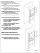
SECURE THE TOP AND THE LEG PORTIONS (STEP 4) ASEGURAR LA TAPA Y LAS PARTES DE PATA (PASO 4) Attached the top portion to the leg by inserting the camlock bolts (3) & the wood dowels (4) located on the top side panels and the lower side panels as shown (Figure 9). Se adjunta la parte superior a la pierna mediante la inserción de los tornillos camlock (3) y las clavijas de madera (4) situados en los paneles laterales superiores y los paneles laterales inferiores como se muestra (Figura 9).
ASSEMBLE OF THE BACK PANEL(STEP 5) ENSAMBLE DEL PANEL POSTERIOR (PASO 5) Attache the back panel ( P) to the assembled top portion using the wood screws (7) as shown (Figure 11). Agregado el panel posterior (P) a la parte superior montado utilizando los tornillos para madera (7) como se muestra (Figura 11).
WALL MOUNT INSTALLATION(STEP 7) INSTALACIÓN MONTAJE EN PARED (STEP 7) Locate a desired position on the wall on which to mount the cabinet. If wall studs are located at the exact screw positions of the cabinet cross bars, then mount the cabinet to the wall using mounting screws (9). If the wall behind the cross bars is hollow, then drill through all mounting holes to mark hole positions on the wall. Remove the cabinet from the wall.