SHELFORD CHANNEL Transformer Gain Mic Pre-amp Inductor EQ & Diode Bridge Compressor Operations Manual
Important Safety Instructions 20. NOTE: This equipment has been tested and found to comply with the Read these instructions. limits for a Class B digital device, pursuant to part 15 of the FCC Rules. Keep these instructions. These limits are designed to provide reasonable protection against Heed all warnings. harmful interference in a residential installation. This equipment Follow all instructions. generates, uses, and can radiate radio frequency energy and, if not Do not use this apparatus near water.
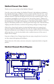
Shelford Channel User Guide Thank you for your purchase of the Shelford Channel. Over fifty years in the making, the Shelford Channel is the definitive evolution of the original technologies in Rupert’s classic console modules like the 1073, 1064, 1081 & 2254, thoughtfully advanced and refined for the 21st century studio.
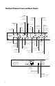
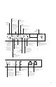
Shelford Channel: Front and Back Panels HPF Freq Selects frequency where the 12 dB per octave high-pass filter begins to roll off low frequency signals. Low Freq Mid Freq 4 position switch selects corner or center frequencies for the low band EQ. 6 position select the center frequency of the mid band EQ stage. Trim Provides continuous gain adjustment, over a range of +/– 6 dB.
Ratio Sets the “slope” of the compression from 1.5:1 to 8:1. Timing 6-position knob for setting the attack/release speed of the compressor. Comp in Engages the compressor. Pre EQ HPF to S/C Routes the HPF from the main signal path into the sidechain removing some amount of low frequencies that the compressor sees.
Power Requirements The Shelford Channel unit has a high quality, low noise switching power supply that is further filtered and regulated for an exceptionally quiet and reliable power source for the audio circuits. The power supply is considered “universal” in the sense that it will accept 100V through 240V AC at 50 or 60Hz. There are no user-accessible fuses in the unit. If your product fails to power on, please contact Rupert Neve Designs technical support.
The Dual Tap Transformer Output with Variable Silk Similar to the input stage, the new output stage is designed to provide the texture and power of Rupert’s classics while allowing for significantly more versatility in tone. The dual-tap output for the Channel’s RN2042 square-core output transformer creates both high- and low-headroom outputs without compromising the Shelford channel’s performance.
The “Best Of The Classics” EQ The 3-band, custom-tapped inductor EQ on the Shelford Channel was inspired by our favorite portions of Rupert’s vintage EQ designs. The low frequency band is primarily based on the 1064 — renowned for its creamy, resonant bass. Unlike the 1064 however, the LF band on the Channel can be used as either a shelf or a peak filter, adding punch, dimension, and immense control to your low end.
The RATIO control has 6 steps between 1.5:1 to 8:1 to achieve a range of compression from subtle to extreme, and the THRESHOLD control has 31 detented steps between -25dBU and +20dBU to handle a wide variety of input levels. MAKE UP GAIN has 31 steps from -6dB to +20dB, and is affected by the blend setting (more on this later). The HPF to SC button moves the Sweepable HPF in the mic pre to the compressor side chain, reducing the impact of low frequencies on the compressor’s response.
Mic Gain This 12-way precision rotary switch controls gain from 0 to 66 dB in 6 dB steps. Trim This detented pot provides further continuous gain adjustment over a range of +/– 6 dB. 48V This push button switch engages phantom power on the microphone input. Please remember to mute or turn down monitors and headphone sends on the channel that the Shelford Channel is plugged into before toggling “+48” (and be especially cautious if you use pre-fader aux sends for headphones).
EQ CONTROLS EQ In This switch engages all EQ frequency bands except the HPF. LF Adjusts up to 15 dB of boost or cut at the selected low frequencies. Cut can be used as a variable, and potentially more gentle alternative to using the HPF. Remember to reduce the signal level at the source to minimize the potential for clipping when any of the 3 bands are boosted significantly.
Mid Freq The MID FREQ rotary switch has 6 positions to select the center frequency of the mid band EQ stage. This circuit utilizes an inductor and capacitors to shape the EQ curve, the same way as Rupert Neve’s console designs of the 70’s. The chosen frequencies are 200 Hz, 400 Hz, 900 Hz, 1.8 kHz, 3.5 kHz and 7.5 kHz. 200 Hz can be especially useful for cuts on individual tracks within a dense mix.
work fine as well. A symptom of a balanced to unbalanced mismatch is that the “compression meter” will indicate a significant change in compression even when the EQ is set flat. Comp In The “COMP IN” button engages the compressor section. Threshold This control sets the level at which the compressor begins to attenuate, variable across a signal level range of -25 dB to +20 dB. With this control fully clockwise, minimal or no compression is achieved.
Timing This six-position controls adjusts the attack/release speed of the compressor. See the “Timing” section on page 18 for timing values. Link Links the side-chain control of multiple units for ganged operation, as would be used for stereo compression. Pre EQ In normal operation, the Compressor follows the EQ so that the Compressor can respond to significant tonal changes caused by the EQ.
OUTPUT CONTROLS VU Select This switch selects either output level or gain reduction metering on the VU Meter. Silk Pushing the Silk button engages the “Silk-Red” circuit, and pushing it a second time introduces “Silk- Blue” circuitry. “Silk” reduces the negative feedback on the output transformer, adding harmonic content as the texture is increased. “Silk Blue” mode features more saturation in the lows and low mids, where as “Silk Red” accentuates the saturation in the high-mids and highs.
Maximum Input +21.5dBu from 150Hz to 22kHz +8dBu 20Hz to 22kHz Gain Steps Position 1 2 3 4 5 6 7 8 9 10 11 12 Gain (dB) 0 6 12 18 24 30 36 42 48 54 60 66 Noise Un-weighted, 22Hz-22kHz, source impedance 150 Ohms balanced. Main Out @ unity gain -6dB Out @ unity gain +30dB gain (Main Out) +66dB Gain (Main Out) Equivalent Input Noise -100.9dBu -106.6dBu -91.37dBu -64.1dBu -121.37dBu Frequency Response +/-0.
Line Input Maximum Input Level +30.5dBu 20Hz to 30kHz Total Harmonic Distortion and Noise @ 1kHz, +20dBu output level, no load. Better than 0.002% @ 20Hz, +20dBu output level, no load. 0.05% Typical (2nd and 3rd harmonic) Noise @ Main Output -101.1dBu Un-weighted, 22Hz-22kHz, source impedance 40 Ohms balanced, no load. Frequency Response +/- 0.25dBu from less than 10Hz to 110kHz -0.
EQ Noise Un-weighted, 22Hz-22kHz, -92dBu Signal Present / Overload Indicator Signal Present Illuminates GREEN when input stage signal level reaches -20dBu Overload Illuminates RED when input stage signal level reaches -23dBu Diode Bridge Compressor Noise (BW 22Hz – 22kHz): 0 dB Makeup Gain: -84.5 dBu +20 dB Makeup Gain: -64.2 dBu Time Constants: Measurements taken represent full range achievable between 1.
Low Frequency Peak Response Audio Precision 07/14/16 16:45:40 +20 +18 +16 +14 +12 +10 +8 +6 +4 d B u +2 +0 -2 -4 -6 -8 -10 -12 -14 -16 -18 -20 10 20 50 100 200 500 1k 2k 5k 10k 20k 50k 100k Hz Sweep Trace Color Line Style Thick Data Axis Comment 1 2 3 4 5 6 7 8 1 1 1 1 1 1 1 1 Cyan Green Red Magenta Magenta Red Green Cyan Solid Solid Solid Solid Solid Solid Solid Solid 3 3 3 3 3 3 3 3 Anlr.Level A Anlr.Level A Anlr.Level A Anlr.Level A Anlr.Level A Anlr.Level A Anlr.
Mid-Band Low Q Frequency Response Audio Precision 07/01/16 13:31:05 +25 +22.5 +20 +17.5 +15 +12.5 +10 +7.5 +5 +2.5 d B u +0 -2.5 -5 -7.5 -10 -12.5 -15 -17.5 -20 -22.5 -25 10 20 50 100 200 500 1k 2k 5k 10k 20k 50k 100k 200k Hz Sweep Trace Color Line Style Thick Data Axis Comment 1 2 3 4 5 6 1 1 1 1 1 1 Cyan Green Red Magenta Blue Cyan Solid Solid Solid Solid Solid Solid 3 3 3 3 3 3 Anlr.Level A Anlr.Level A Anlr.Level A Anlr.Level A Anlr.Level A Anlr.
Mid-Band High Q Frequency Response Audio Precision 07/01/16 13:40:06 +25 +22.5 +20 +17.5 +15 +12.5 +10 +7.5 +5 d B u +2.5 +0 -2.5 -5 -7.5 -10 -12.5 -15 -17.5 -20 -22.5 -25 10 20 50 100 200 500 1k 2k 5k 10k 20k 50k 100k 200k Hz Sweep Trace Color Line Style Thick Data Axis Comment 1 2 3 4 5 6 1 1 1 1 1 1 Cyan Green Red Magenta Blue Cyan Solid Solid Solid Solid Solid Solid 3 3 3 3 3 3 Anlr.Level A Anlr.Level A Anlr.Level A Anlr.Level A Anlr.Level A Anlr.
High Frequency Peak Audio Precision 07/14/16 17:05:45 +22.5 +20 +17.5 +15 +12.5 +10 +7.5 +5 +2.5 d B u +0 -2.5 -5 -7.5 -10 -12.5 -15 -17.5 -20 -22.5 10 20 50 100 200 500 1k 2k 5k 10k 20k 50k 100k 200k Hz Sweep Trace Color Line Style Thick Data Axis Comment 1 2 3 4 1 1 1 1 Cyan Green Red Green Solid Solid Solid Solid 3 3 3 3 Anlr.Level A Anlr.Level A Anlr.Level A Anlr.
HPF Frequency Response Audio Precision 07/01/16 09:22:01 +6 +4 +2 -0 -2 -4 -6 -8 d B u -10 -12 -14 -16 -18 -20 -22 -24 -26 -28 -30 20 50 100 200 500 1k 2k 5k 10k 20k 50k 100k 200k Hz Sweep Trace Color Line Style Thick Data Axis Comment 1 2 3 1 1 1 Cyan Green Magenta Solid Solid Solid 3 3 3 Anlr.Level A Anlr.Level A Anlr.Level A Left Left Left Baseline HPF @ 20Hz HPF @ 250Hz 810-00042(ShelfordCh) HPF Freqeuncy Response Line Input to Main Output Z-Out = 40 Ohms FreqResp_HPF.
PRODUCT WARRANTY Rupert Neve Designs warrants this product to be free from defects in materials and workmanship for a period of one (1) year from date of purchase, and agrees to remedy any defect identified within such one year period by, at our option, repairing or replacing the product.