5051 By: Inductor EQ / Compressor Serial #: Operations Manual 1
5051 Inductor EQ / Compressor Thank you for your purchase of the 5051 Inductor EQ / Compressor. Everyone at Rupert Neve Designs hopes you enjoy using this tool as much as we have enjoyed designing and building it. Please take note of the following list of safety concerns and power requirements before the use of this product. Safety It’s usual to provide a list of “do’s and don’ts” under this heading but mostly these amount to common sense issues.
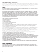
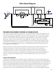
5051: Front Panel 5051 EQ/Compressor INDUCTOR EQ High Frequency Shelf / Peak 0 LINE 1 LINE 2 Selectable at 8 and 16 Khz. With continuous gain from -15 to +15dB. Selectable peak or shelf curves Mid Parametric Selectable at 200, 350, 700, 1.5 K, 3 K, and 6 KHz. With continuous gain from -15 to +15dB. Selectable Hi Q. EQ IN -15 HF +15 3K 1.
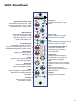
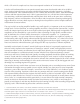
5051: Back Panel S/C INSERT S/C Insert Sends and returns a side chain signal to the compressor VCA. The return input can be used as a “key” input for the compressor. Note: The S/C insert is a half-normal connection, so if there is no signal on the S/C insert return when it is plugged in, there will not be any compression.
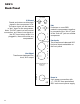
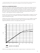
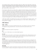
051: Block Diagram EQ Pre/Post EQ In IP 1 Inpu t Tran sformer Input Select IP 2 Compressor In Ou tpu t Meter Ou tpu t Tran sformer HPF In Mid Band VCA Shelves HPF Link Compressor S/C Thresh Attack Ratio Release G ain FF/FB S/C Send/Return HPF Redu ction Meter THE NEED FOR DYNAMIC CONTROL OF SOUND LEVELS The dynamic range of sounds we hear around us in normal life greatly exceeds the capability of our best recording and processing equipment - but even if this were not so, the scale of dyna
while a CD at 44.1k sample rate has a best-case temporal resolution of 23 microseconds). It is also well understood that we can perceive steady tones even when buried under 20 to 30 dB of noise. And we know that most gain stages exhibit rising distortion at higher frequencies, including more IM distortion. One common IM test is to mix 19 kHz and 20 kHz sine waves, send them through a device and then measure how much 1 kHz is generated (20-19=1).
3. Miland Kunchur,Depart of Physics and Astronomy, University of South Carolina.Probing the temporal resolution and bandwidth of human hearing , M. N. Kunchur, Proc. of Meetings on Acoustics (POMA) 2, 050006 (2008) HOW THE 5051 COMPRESSOR WORKS A part of the audio signal is rectified and smoothed to produce a suitable control voltage for the VCA. which has to respond very quickly and have low distortion.
“knows” right away that a gain change is required and there is an almost immediate response. This is known, logically, as a “feed-forward” compressor. If the VCA control voltage is taken from the 5051 compressor output, (i.e. after the VCA) it cannot act immediately on the VCA because it has already been modified by settings of the VCA and circuits through which it has passed. This is known as a “feed-back” compressor.
The compressor likewise contains some elements of the past, utilizing Class A gain blocks, mixed with the gain reduction techniques that have been developed over the years and is similar to the Master Buss Processor. The threshold has a range of -30 dBu to +20 dBu. The ratio can be set from 1.1:1 to 40:1. The attack has a range of 5 ms to 75 ms, and the release is variable from 100 ms to 2.5 s to be set. Make-up gain can be set from -6 dB to +20 dB.
console designs of the 70’s. The frequencies chosen are 200 Hz, 350 Hz, 700 Hz, 1.5kHz, 3 kHz and 6 kHz. 200 Hz is especially useful for cuts on individual tracks within a dense mix. MID HI Q The resonance or Q of the mid band at maximum boost is typically 2 when the button is out. When the MID HI Q is pressed at maximum boost, the Q narrows to approximately 3.5. The Q widens nicely with less boost or cut as is typical for passive EQ circuits.
Adjusts the final output level of the compressor, and is operationally the same as “Make-Up Gain”. Gain is used to restore the signal back up to a relatively normal level, and is often used to finely control sending the final signal level, for example, to an analog to digital converter. S/C HPF Engages a 250Hz, 12dB per octave high pass filter to prevent low frequency material from excessively controlling the compressor.
let the output rise by 1 dB implying 9 dB of compression, 2:1 will cause the output to increase 5 of those initial 10 dB suggesting 5 dB of reduction. Some engineers relate ratios of 20:1 and higher with limiting, however technically traditional limiting also requires very fast attack times to respond to transients and prevent signals from actually going above a certain level. COMP IN Engages the compressor, and is indicated by a green button.
compression. LINK IN / OUT 1/4” phone jacks on the back used to connect the compressor VCAs. The suggested setup for linking multiple units is to do the following: On the back panel of the left most 5051, plug the link cable into the link out jack. Plug the other end of the cable into the link in jack of the 5051 to its right. In the same way, connect all of the 5051 units together. LINE 1 XLR female transformer balanced floating input associated with the LINE 1 position of the front panel input switch.
@ 20kHz, +20 dBu out Better than 0.010% Equalizer Noise: Measured at Main Output, unweighted, 22Hz-22kHz, Terminated 40 Ohms. with all gains set at 0, Better than –92 dBu Maximum input: from 20 Hz to 20 kH, +24.5 dBu Maximum output: from 20 Hz to 20 kHz, +24.5 dBu Total Harmonic Distortion and Noise: from <10 Hz to 80 kHz, @ 1kHz, +20 dBu output: Better than 0.007% @ 20Hz, +20 dBu out Better than 0.120% @ 20kHz, +20 dBu out Better than 0.070% The Compressor (Threshold at +20 dB, Ratio at 1.
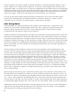
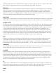
High Pass Filter +20 +15 +10 +5 d B u +0 -5 -10 -15 -20 -25 10 20 50 100 Sweep Trace Color Line Style Comment 1 2 3 1 1 1 Red Magenta Blue Solid Solid Solid Bypass 60 Hz 120 Hz 200 500 1k Hz 2k 5k 10k 20k 50k 200k Low Frequency EQ +20 +15 +10 +5 d B u +0 -5 -10 -15 -20 10 20 50 100 Sweep Trace Color Comment 1 2 3 4 5 6 7 8 9 1 1 1 1 1 1 1 1 1 Red Cyan Cyan Green Green Magenta Magenta Red Red EQ Flat 35 Hz Full Boost 35 Hz Full Cut 60 Hz Full Boost 60 Hz Full Cut 100 Hz F
Mid Band EQ +20 +15 +10 +5 +0 d B u -5 -10 -15 -20 -25 10 20 50 100 Sweep Trace Color Comment 1 2 3 4 5 6 7 8 9 1 1 1 1 1 1 1 1 1 Red Magenta Magenta Magenta Magenta Cyan Cyan Cyan Cyan Flat 200 Hz Full Boost 200 Hz Full Boost Hi Q 200 Hz Full Cut 200 Hz Full Cut Hi Q 350 Hz Full Boost 350 Hz Full Boost Hi Q 350 Hz Full Cut 350 Hz Full Cut Hi Q 200 500 1k Hz 2k 5k 10k 20k 50k 200k 20k 50k 200k High Frequency EQ +25 +20 +15 +10 +5 d B u +0 -5 -10 -15 -20 -25 10 16 20 50 100
PRODUCT WARRANTY Rupert Neve Designs warrants this product to be free from defects in materials and workmanship for a period of one (1) year from date of purchase, and agrees to remedy any defect identified within such one year period by, at our option, repairing or replacing the product.