
Owner's Manual


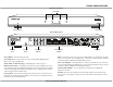
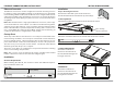
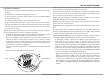

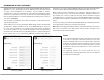
Table Of Contents

6 XZone4 Installation Manual
ETHERNET CONNECTION AND FACTORY RESET
Ethernet Connection
The Ethernet connection is used for conguration and audio streaming as well as
for enabling control via the MyRussound App or the XTS Touchscreen. The default
network setting is DHCP-enabled, but the XZone4 can be congured with static IP
addressing using Web Cong. The Ethernet connection is also used for the built-in
streaming services and for playing any music stored on connected network drives
using DLNA.
Note: While the XZone4 has a single physical Ethernet connection, it will occupy
a total of 5 IP addresses on the network. One address is for XZone4 management,
and there are four other addresses, one for each of the internal streaming modules
that the XZone4 utilizes to provide independent streaming audio content to each
zone. If using DHCP, all 5 addresses will use DHCP. If using static IP addressing, all
5 addresses will need to be congured with a static address.
Factory Reset
The factory reset button has two functions. A 3-second press and hold will restore
network settings to DHCP. A 10-second press and hold will reset the XZone4 to
its factory default settings. When performing either of these functions, do not
power o the XZone4. It will reboot automatically on its own at the proper time.
The entire reset process may take several minutes. The XZone4 status LED will
illuminate green when the process is complete.
The factory reset deletes all conguration and personal information including
service account settings and passwords.
Note: After a factory reset, the XZone4 will require valid Russound Certied
Installer credentials in order to be unlocked and congured again.
INSTALLATION OVERVIEW
Installation
Step 1. Mounting the XZone4
The XZone4 comes with a pair of rack mount ears,
that allows XZone4 to be mounted in any of four ways:
Installation
Clearance Requirements
When installing the XZone4, the clearances shown here MUST be kept for
proper ventilation of the unit.
2. Rack Mount
Attach the included rack mount ears to both sides of the unit as shown.
3. Under Cabinet Mount
Attach the included rack
mount ears to both sides of
the unit, with mounting holes
facing up as shown.
4. Wall Mount
Attach the included rack
mount ears to both sides of
the unit, with mounting holes
facing down as shown.
Top of the unit
Rack mount ear
4 Non-marking
adhesive rubber feet
1. Table Top Mount
Attach the four adhesive backed feet to the bottom of the chassis
1.75” (4.4cm)