4-Source Multi-Zone Central Audio Controller/Amplifiers CAi-Series Instruction Manual ROCK R&B JAZZ CHILDRENS VOLUME • ON / OFF • VOLUME • SOURCE SOURCE STORE POWER REMOTE SENSOR Patented REMOTE SENSOR CA-KP.2 CA-LCD.2 CA 6.4i 6-Zone, 4-Source Central Controller/Amplifier CA6.4i 6 Zone — 4 Source Central Controller/ Amplifier 1 2 3 4 5 6 Z ONE P OWER CA 4.4i 4-Zone, 4-Source Central Controller/Amplifier CA4.
IMPORTANT SAFEGUARDS “WARNING” “ TO REDUCE THE RISK OF FIRE OR ELECTRIC SHOCK, DO NOT EXPOSE THIS APPLIANCE TO RAIN OR MOISTURE.” “CAUTION” “ TO REDUCE THE RISK OF ELECTRIC SHOCK, DO NOT REMOVE COVER. NO USER - SERVICEABLE PARTS INSIDE. REFER SERVICING TO QUALIFIED SERVICE PERSONNEL.
CONTENTS Product Overview . . . . . . . . . . . . . . . . . . . . . . . . . . . . . . . . .4 Possible System Configurations . . . . . . . . . . . . . . . . . . . . . .4 Unpacking and Warranty . . . . . . . . . . . . . . . . . . . . . . . . . . . .4 Getting Started . . . . . . . . . . . . . . . . . . . . . . . . . . . . . . . . . . .5 Tools Needed . . . . . . . . . . . . . . . . . . . . . . . . . . . . . . . . . . . . . .5 Basic Planning and Layout Considerations . . . . . . . . . . . . .5 Connection Tips .
PRODUCT OVERVIEW Congratulations on your recent purchase of a Russound CAi-Series multi-room controller. This four/six-zone, four-source, multi-room controller is the heart of an affordable whole-house audio distribution system. High-current, stereo, power amplifiers are built into the Russound CAi allowing simple connections to each speaker in the system. Each zone is operated by an intuitive, easy-to-use keypad that controls all the functions of the CAi.
GETTING STARTED TOOLS NEEDED The following information will indicate some tools and materials necessary for a complete installation: • 4 twisted pair communication wire (commonly referred to as CAT-5). This wire will be used to connect the keypads in each zone to the controller. Stranded, 16 Gauge minimum, CL3 rated wire. This wire is used for direct connection between the CAi and your speakers. • 110 Punchdown tool (included) • A medium sized flat-head screwdriver.
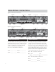
REAR PANEL CONNECTIONS Figure 3 - CA6.4i Rear Panel Connections Source Input Connections CA6.4i NEWMARKET, NH U.S.A.
REAR PANEL CONNECTIONS ZONE PRE-AMP OUTPUTS MUTE VARIABLE Switch in VARIABLE Position: In applications where more power than the 20 watts per channel is desired, connect one or more zones of the FIXED CAi to an external amplifier. Using standard RCA connectors, wire from the pre-amp outputs of the CAi to the amplifier's inputs. A typical application for more power is when connecting an outside zone where the audio power requirements would be much greater than an inside zone.
KEYPAD CONNECTIONS AT CONTROLLER • Each keypad connection on the back panel of the CAi-Series Master Controller corresponds to the room / zone number chosen for your speakers. Each zone operates independently, so it is very important to connect the keypad to the correct zone keypad input. • On List 4 (opposite) copy down the room name to the zone number from List 3 on pg 6. NOTE: the keypad and the speakers in each room must be hooked to the corresponding numbered zone.
INSTALLING KEYPADS PUNCHDOWN TERMINALS INSTALLING THE KEYPADS Figure 11 – Punchdown Terminal on CAi keypad The CAi Keypads come with 110 punchdown terminals. These terminals are quick, easy to install and provide a strong connection. Punchdown terminals require the use of a punchdown tool. One has been provided with this kit. Press wires into punchdown terminal with punchdown tool as shown in Figure 12. Figure 12 – Punching Down Wires VOL BAL SEL1 SEL3 CH SEL +12V Connector on CA-KP.2 or CA-LCD.
INSTALLING KEYPADS SETTING THE KEYPADS INFRARED KEYPAD PROGRAMMER — IKP-1 Before a keypad is installed into the j-box, turn on the power so that you can operate the keypad. CA-LCD.2 Only: The amber and the green backlight brightness can be individually set. Note the brightness controls are located on the side of the keypad. Adjust to the desired brightness the backlight that first comes on. Press and hold the lamp button on the front of the keypad until the backlight switches to the other color.
SPEAKER INSTALLATION SRM-2.1 SPEAKER RELAY MODULE OPTION The optional SRM-2.1 module works with CA-LCD.2 keypad’s 12V trigger output. This unobtrusive wall-mount device allows you to automatically switch to whole house audio in a zone containing existing audio equipment. Example: In a bedroom with a stereo system, the stereo system would be the default. When you turn on the bedroom's zone at the keypad the whole house audio system takes control of the existing stereo speakers.
OPERATION OPERATING THE MAIN UNIT OPERATING THE CA-KP.2 KEYPAD • Power switch: When the power switch is engaged, the CAi power indicator will be lit an amber color. The CAi should be left on at all times. The unit will consume very little power unless the zones are on and active. The unit has a stand-by mode when the zones are inactive. • Zone Indicators: The zone indicator will light either red for off or green for on. The zones can only be turned on from the keypads.
OPERATION OPERATING THE CA-LCD.2 KEYPAD 1) Display: The LCD panel displays the name of the source selected and the volume level. 2) Source: The source button is pressed to select one of the four sources to listen to. Press the source button until the desired source is selected. The source will be displayed on the LCD display panel. 3) Volume Up / Down: The UP / DOWN arrows for volume are used to select the volume level and to select a different source name after the store button is pressed.
SPECIFICATIONS CA6.4i CA4.4i • Frequency Response: 20 Hz to 20 KHz ( +/- 1 dB ) • 20 Watts RMS / Channel @ 8Ω • 12 Channels / 6 Stereo Amplifiers • Total Harmonic Distortion: .01% • Signal to Noise Ratio: 89 dB min, “A” weighted • Power Supply: 110/220V High Current Torroidal • ETL listed. Conforms to UL Standard UL1492 and CSA Standard C22-2 No.
TROUBLESHOOTING COMBINING ADDITIONAL IR RECEIVERS When combining a CAi Series multi-source controller and a secondary IR system together, it needs to be done after the CAi System. The IR information from the keypad is on Pin #2. This signal is demodulated at the keypad and is re-modulated at the processor then sent to the emitter out-puts. Combining a modulated IR signal to this lead (#2) will not work because it is already modulated.
A / V D I S T R I B U T I O N & C O N T R O L S Y S T E M S 5 Forbes Rd. Newmarket, NH 03857 ☎ 603.659.5170 • Fax 603.659.5388 e-mail: tech@russound.