CAM6.
IMPORTANT SAFEGUARDS 9. Heat - The appliance should be situated away from heat sources such as radiators, heat registers, stoves, or other appliances (including amplifiers) that produce heat. 10.Power Sources - The appliance should be connected to a power supply only of the type described in the operating instructions or as marked on the appliance. WARNING: TO REDUCE THE RISK OF FIRE OR ELECTRIC SHOCK, DO NOT EXPOSE THIS APPLIANCE TO RAIN OR MOISTURE. 11.
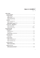
TABLE OF CONTENTS USER SECTION Product Introduction ............................................................................................................6 Component Guide CAM6.6 Controller...............................................................................................................7 UNO-S1 Keypad ..................................................................................................................8 UNO-S2 Keypad (Optional).................................................
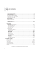
TABLE OF CONTENTS Source IR Input Connections ..............................................................................................30 Common IR Input Connection .............................................................................................31 Speaker Connections ........................................................................................................32 Zone Fixed/Variable Audio Output .....................................................................................
USER SECTION Component Guides Explains front panel features of the CAM6.6 controller, UNO-S1 keypad, optional UNO-S2 keypad and UNO-LRC1 remote control. Operation Step-by-step outline of the system's normal operation, plus a look at adjustable features available through the User Menu.
PRODUCT INTRODUCTION Thank you for choosing the Russound® CAM6.6T-S1 System to enhance your home with distributed audio. This system’s state-of-the-art features and components blend seamlessly with your unique lifestyle and preferences. Besides distributing and controlling six audio sources to six rooms (zones), your CAM6.6T-S1 System offers many features that increase your enjoyment of living. Here are several that you may find particularly beneficial. Internal Source The CAM6.
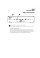
USER COMPONENT GUIDE CAM6.6 Controller-Front Panel 1 2 1 MAIN POWER SWITCH - Supplies power to the CAM6.6 2 ROOM LED ON/OFF INDICATORS - Indicates when a room is on (green) or off (red) Main Power and Zone Status The power switch for the CAM6.6 controller is “on” in the up position. Any active room (1-6) is indicated on the front of the controller by a green LED, which shows red when the room is inactive.
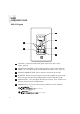
USER COMPONENT GUIDE UNO-S1 Keypad 1 102.5 2 6 3 5 4 1 LCD PANEL - 5-character backlit display shows status of the room, source, volume, and more 2 SOURCE SELECT BUTTON - Scrolls through the sources directly connected to the CAM6.6. Press and hold brings up the USER MENU for loudness, bass, treble, etc. 3 VOLUME UP/DOWN BUTTONS - Raises and lowers the volume for the room 4 IR RECEIVER - Receives IR signals and passes them to the controller and source equipment.
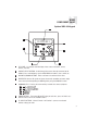
USER COMPONENT GUIDE Optional UNO-S2 Keypad 1 7 CD PLAYER 1 2 6 3 5 4 1 LCD PANEL - 12-character backlit display shows status of the room, source, volume, and more 2 SOURCE SELECT BUTTON - Scrolls through the sources directly connected to the CAM6.6. Press and hold brings up the USER MENU for loudness, bass, treble, etc. 3 VOLUME UP/DOWN BUTTONS - Raises and lowers the volume for the room 4 IR RECEIVER - Receives IR signals and passes them to the controller and source equipment.
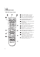
USER COMPONENT GUIDE UNO-LRC1 Remote Control 2 3 4 1 LOCAL DEVICE BUTTONS - Select local source to be controlled by UNO-LRC1. 2 SETUP - Use for programming UNO-LRC1 using the built-in library or by learning-in codes. 3 UNO SOURCE BUTTON - Selects UNO Keypad for control by UNO-LRC1. 4 ROOM ON/OFF - Turns room on and off while in the UNO mode. 5 NUMBER BUTTONS - Buttons (0-9) for direct selection of channels or tracks. 6 INPUT - Scrolls through sources connected to the CAM6.
USER OPERATION UNO-S1 Keypad Zone On/Off Press and release used to enter the User Menu with a press and to turn on the UNO System Keypad. This also turns on the corresponding CAM6.6’s room, and any presets previously assigned will be activated, including settings for bass, volume, last source selected, etc. Press and release to turn off the UNO System Keypad. This will also put the corresponding CAM6.6’s room into a standby state. hold action.
USER USER MENU SETTINGS UNO-S1 User Menu Operation The User Menu allows the user to adjust the audio properties and control functions of a particular room. To enter or exit the User Menu, press and hold during normal operation. The following keys are used to navigate and make changes while using the User Menu: Press and hold to adjust feature setting (increment) Press and hold to adjust feature setting (decrement) Go to next feature. Go to previous feature. View current feature setting.
USER OPERATION Optional UNO-S2 Keypad Zone On/Off Press and release used to enter the User Menu with a press and to turn on the UNO System Keypad. This also turns on the corresponding CAM6.6’s room, and any presets previously assigned will be activated, including set- hold action. (See next page for User Menu) Volume Up/Down Buttons The room’s audio output is adjusted using . tings for bass, volume, last source selected, etc. Press and release to turn off the UNO F1 and F2 Buttons System Keypad.
USER USER MENU SETTINGS Optional UNO-S2 User Menu Operation The User Menu allows the user to adjust the audio properties and control functions of a particular room. The following keys are used to navigate and make changes while using the User Menu: To enter the User Menu, press and hold during normal operation. To exit the User Menu, press and release . Adjust feature setting (decrement). Go to next feature. Go to previous feature. View current feature setting.
USER INTERNAL SOURCE - AM/FM TUNER UNO-S1 Keypad Control UNO-S1 Keypad Control of Tuner Selecting the desired frequency Selecting the tuner Press and hold On the UNO-S1 keypad, press to select the or tuning. Once active, press to activate manual or to scroll AM/FM tuner by choosing the tuner’s preas- through frequencies. The frequency will scroll signed source number (1). twice on the keypad then stop and display the station’s first 5 characters. 102.
USER INTERNAL SOURCE - AM/FM TUNER UNO-S2 Keypad Control UNO-S2 Keypad Control of Tuner of six called banks, and there are six banks. Selecting the tuner Each preset and each bank can be given a cus- On the UNO-S2 keypad, press to select the tom name of your choice. AM/FM tuner by choosing the tuner’s preas- To select a bank, press and hold signed source number (1). up or for bank for bank down. The bank’s name will be temporarily displayed on the UNO-S2.
USER INTERNAL SOURCE - AM/FM TUNER UNO-S2 Keypad Control 1 6 92.
USER INTERNAL SOURCE - AM/FM TUNER UNO-LRC1 Remote Control UNO-LRC1 Control of Tuner Frequency Scan Selecting the tuner To scan, press and hold then release To select the tuner, push and choose the . The tuner scans through tuned stations with a 5-second source number preassigned to the AM/FM tuner (1), preview before moving to the next station. To end or use the UNO numeric source inputs at the bottom scanning, press of the UNO-LRC1.
USER INTERNAL SOURCE - AM/FM TUNER UNO-LRC1 Remote Control UNO SELECTION - UNO must be the selected source for control of the CAM6.6 and any connected components. Select UNO before sending UNO-LRC1 remote commands. 1 POWER - Power managed by CAM6.
CAUTION Do not connect the controller's main power feed until all other connections have been made and verified. Live connection or removal of the keypad wiring or other wiring when the system is powered can cause communication problems in the network. Double-check terminations during each phase of the installation to prevent accidental damage. Incorrect wiring is the number one cause for non-warranty product damage.
INSTALLER SECTION Getting Started Includes an installation overview, including tools needed and wiring instructions. Component Guides Reviews front and back panel features of the CAM6.6 controller and the UNO-S1 keypad. Keypad Installation Explains UNO-S1 keypad installation and wiring. Making Connections Details front and back panel connections of the controller and the keypad.
INSTALLER GETTING STARTED Unpacking the System Components • Keep the original carton and packing materials for future shipment or storage. • Check for any visible signs of damage. If you encounter any concealed damage, consult your Russound dealer before proceeding to install the unit. • Retain the sales receipt as it establishes the duration of the limited warranty and provides information for insurance purposes. CAM6.6T-S1 System Components: • 1 (one) CAM6.
INSTALLER WIRING INSTRUCTIONS RJ-45 Connections The CAT-5 T568A wiring standard shown on the right is used for the RJ-45 terminations. Keypad Wiring For the UNO-S1 keypad, the following connections are used to terminate the CAT-5 wire to the 110 punchdown on the keypad: CAT-5 WIRE COLOR TYPE • Confirm ahead of time that you can drill an outlet hole easily and in an unobtrusive spot to connect wires with the CAM6.6. • Label wires with keypad and room location. This simplifies CAM6.
INSTALLER COMPONENT GUIDE CAM6.6 Controller-Rear Panel 1 2 3 4 5 6 7 8 9 10 11 CAM6.6 19 20 24 18 17 16 15 14 13 12 1 RNET LINK IN AND LINK OUT - Links multiple CAM6.6’s, also links future Russound components that are RNET compatible 2 RS-232 INTERFACE - The RS-232 Interface allows the zones to be controlled by PC or other devices that have an RS-232 Interface. The RS-232 Interface also allows for firmware updates and programming.
INSTALLER COMPONENT GUIDE CAM6.6 Controller-Rear Panel 10 OPTIONAL INTERNAL SOURCE - Factory installed optional internal source, AM/FM radio module 11 AC 240V-AC 110V Switch - Switches A/C input voltage between 110VAC and 240VAC 12 AC 120/240 INPUT - Grounded 3-terminal plug detachable power cord connection for the CAM6.6 13 FUSE HOLDER - Holds a replaceable fuse for A/C input connection 110VAC operation - F 3A H 250V, 240VAC operation; T 1.
INSTALLER COMPONENT GUIDE UNO-S1 Keypad-Update Port 1 Src 3 3 2 Data Rx TTL Level Data Tx TTL Level GND +12VDC Note: Do not put RS-232-level signals into the pins. Must use Advanced Programming Cable P/N 2500-521065. 26 1 OS Update/Run Jumper -The pins are jumpered when performing an OS update on the keypad, and removed during normal operation. (Typically needed only on a keypad that has never been updated) 2 Setup Button - Activates information and update menus for the keypad.
INSTALLER COMPONENT GUIDE UNO-S1 Keypad-CAT-5 Connection CAT-5 Connection The UNO-S1 Keypad uses a 110-punchdown terminal to provide a simple installation and strong connection for CAT-5 cable’s eight conductors. Punchdown terminals require the use of a punchdown tool which has been provided with the keypad kit. Attach the CAT-5 cable to the 110-punchdown terminal on the UNO-S1 Keypad as shown, matching the conductor colors to the connection color guide.
INSTALLER UNO-S1 KEYPAD-INSTALLATION Keypad Location The best infrared remote performance is achieved with the keypad away from any direct sunlight, plasma TV, and low voltage lighting controls. Also consider convenience when choosing a location. Choose a place that is easily seen from the position where a person is most likely to be located. Check whether or not you can route the wire to the location you have chosen.
INSTALLER MAKING CONNECTIONS UNO-S1 Keypad Port Connection The UNO System Keypad Ports are located on the back of the CAM6.6 in the top left of center. Connections made at the UNO Keypad Ports are made using CAT-5 T568A RJ-45 wire configuration. CAT-5 is color-coded for ease of installation. For a clean installation when wiring from an UNO System Keypad Port use an RJ-45 CAT-5 patch cable to connect from the keypad port to an RJ-45 Wall Plate (optional).
INSTALLER MAKING CONNECTIONS Source Audio and IR Input Connections Source Audio Connections The CAM6.6 supports up to six audio sources. The Source Inputs are located at the back panel. The Source 1 input serves a dual purpose. If the CAM6.6 optional internal source is used, the Source 1 input is not available, and the switch next to it is set to “Internal Source Output.
INSTALLER MAKING CONNECTIONS Common IR Connection Common IR Connections The Common IR jack on the rear of the CAM6.6 allows control of any source equipment without that source being selected on the keypad. The connection for the COM IR jack is made using an IR emitter with a 1/8’’ plug. The Russound 845.1 single IR emitter is recommended, or use an IR connecting block such as the Russound 857 which allows multiple units to be controlled through the COM IR Port. CAM6.
INSTALLER MAKING CONNECTIONS Speaker Connections The speakers are connected to the CAM6.6 using modular snap connectors. Each of these color-coded connectors is designated for the speaker set of a particular amplified zone. To avoid confusion, connect one zone speaker set at a time starting with Zone 1, taking care to keep zone and speaker wire identities straight. Note: An 8 Ohm minimum speaker is required for each amplified output.
INSTALLER MAKING CONNECTIONS Zone Fixed/Variable Audio Outputs The CAM6.6 has two Zone Audio outputs, on Zone 1 and Zone 2. Each of these zone audio output connections features a stereo line out RCA connection plus a switch to allow for either a fixed or a variable line level output. When set to Variable, the keypad volume level affects this output. In the Fixed position, the keypad volume level will not change the output level.
INSTALLER MAKING CONNECTIONS 12VDC Home Theater Trigger In/Out 12VDC Home Theater Trigger In This 12VDC Trigger input is used to control Power Management of the audio sources possibly being shared with a home theater system. When the last zone on the CAM6.6 is turned off, 12VDC presence to the trigger input will prevent the sources that are on from being turned off. The connections for the trigger are made using a twoconductor cable with 1/8” male mini-plug.
INSTALLER MAKING CONNECTIONS 12VDC Mute Trigger In/Out 12VDC Mute Trigger In When 12VDC is applied to the Mute Trigger In, the system will fully mute any source that is connected to the Source Audio Input. The connections for the trigger are made using a two-conductor cable with 1/8” male mini-plug jacks. The tip is positive (+) and sleeve is negative (-). This allows for the connection of an external paging or muting device. The CAM6.
INSTALLER MAKING CONNECTIONS RNET Link In and Link Out The RNET Link In and Link Out can be used to connect two to six CAM6.6 or CAV6.6 controllers. The connection is made using a CAT-5 patch cable from the Link Out of the master CAM6.6 and into the Link In of the next controller. Along with RNET data signals, the RNET Link In and Link Out jack passes the six source IR signals. These are only for source-specific IR remote repeating, not codes initiated from the controller’s internal IR library.
INSTALLER MAKING CONNECTIONS RS-232 Interface The CAM6.6 supports RS-232 communication with various third party automation systems or PC for programming of the controller. The RS232 com port is located on the back of the CAM6.6 and uses a DB-9 cable connection. For RS-232 protocol and the backup PC application, see the Document Center at www.russound.com. Look for the Technical Documents under Multi-source/Multi-room products. CAM6.
INSTALLER MAKING CONNECTIONS Optional Internal Source - AM/FM Tuner Antennas AM Antenna FM Antenna Connect the included loop antenna for AM reception to the Optional Internal Source panel, attaching the GND (ground) and AM ends to the appropriately marked connections. Attach the included FM antenna for FM reception to the Optional Internal Source panel by pushing the F-type quick-connect termination of the antenna onto the FM connection. CAM6.
INSTALLER MAKING CONNECTIONS Optional Internal Source - AM/FM Tuner Antennas Connecting an Alternate Outdoor Antenna for AM/FM The diagram below depicts a suggested installation option of an alternate outdoor FM antenna and AM antenna. For best performance for AM reception, it is recommended to use an external outdoor or atticmounted long wire antenna for best performance for AM reception. Use a 75-ohm to 300-ohm balun at the AM connection on the tuner, and attach the 75-ohm coax cable to the balun.
INSTALLER MAKING CONNECTIONS Grounding Outdoor Antennas Antenna Lead In Wire Electric Service Equipment Grounding Conductors Ground Clamps Grounding an Outdoor Antenna If the tuner is used with an outdoor antenna, the antenna must be grounded against static charges and voltage surges. Consult the instructions that came with the antenna or contact the antenna manufacturer for proper installation instructions.
INSTALLER INITIAL INSTALL TEST Before proceeding to the system programming section, it’s important to conduct an initial test to determine that the hardware components are working properly. 1. Connect the speaker wires from Zone #3 to the CAM6.6 Zone #3 speaker output connectors. 2. Connect an UNO-S1 keypad to Keypad Port #3 on the rear of the CAM6.6. 3. Connect a source to the Source #3 Input on the CAM6.6 using RCA Audio patch cables. 4. Plug a supplied 845.
INSTALLER SYSTEM PROGRAMMING OVERVIEW This manual includes items that are designed to assist in the programming process. Forms (Pages 44-46) Three blank reproducible forms are included as planning tools when determining sources, settings and zone preferences. The Source and Zone Information forms and the Macro Editor form should be completed before programming and referred to during the installation menu process. This speeds up programming time and reduces missed or incorrect entries.
INSTALLER SYSTEM PROGRAMMING OVERVIEW 3. Basic Setup (SOURCE SETUP) (Pages 50-52) This procedure is mandatory to set up each source for keypad source control and is the cornerstone of the programming process. 4. Peripheral Setup (Pages 48-50) (FOR OPTIONAL INTERNAL SOURCE) This procedure provides setup and naming procedures for the tuner. It includes assigning a custom name to a memory preset or bank, and choosing a region for AM/FM operation (US or Euro). 5.
N/A N/A N N/A N N/A Peripheral N/A Russound Tuner INSTALLER SETUP FORMS
INSTALLER Mute SETUP FORMS 45
INSTALLER SETUP FORMS 46
INSTALLER INSTALLATION MENU OVERVIEW There are three item types in the installation menu: Menu Item – Procedure – Feature – Acts as a folder that holds procedures and/or feature parameters. A sequence of feature parameters to perform a guided operation, such as configuring an UNO key. Once you begin a procedure, the system will prompt for the information needed to complete the task. The actual parameters (settings) that will change the system configuration.
INSTALLER INSTALLATION MENU The following items make up the Installation Menu: PERIPH SETUP (PerSu) SOURCE SETUP (SrcSu) CTRLR SETUP (CtlSu) POWER MGT (PwMgt) MACRO EDITOR (MacEd) ZONE SETUP (ZonSu) LEARN IR (LrnIR) SYSTEM INFO (SInfo) PERIPH SETUP (PerSu) Peripheral Setup allows the CAM6.6’s optional internal source to be configured.
INSTALLER INSTALLATION MENU 2. BANK NAME – (BnkNm) Use the volume up/down keys to select a character and left/right keys to change a character position. A blinking cursor indicates placement of the character being entered. Names can be from 1 to 5 characters in length. If adding names from 6-12 characters, it is suggested you use an optional UNO-S2 keypad. CONTROLLR ID (CtlId) This procedure is used to identify the controller(s) that the tuner will respond to. See Periph Setup Flow Chart on page 64 1.
INSTALLER INSTALLATION MENU SYSTEM INFO (SInfo) System Info shows the tuner’s manufacturing build properties. See Periph Setup - Flow Chart on page 64 BUILD TIME (BTime) BUILD DATE (BDate) VERSION (Ver) 1. BUILD TIME (BTime) Displays the firmware Build Time of the tuner. 2. BUILD DATE (BDate) Displays the firmware Build Date of the tuner. 3. VERSION (Ver) Displays the firmware version of the tuner. SOURCE SETUP (SrcSu) Source Setup allows the system’s sources to be configured.
INSTALLER INSTALLATION MENU 2. SOURCE NAME – (Name) Select the name for the source (e.g., DVD, Aux 2, Jazz, etc.). 3. COMMAND TYPE – (CmdTp) Select the type of command template (e.g., CD, TV, etc.). Selecting the command type template will tell the CAM 6.6 how to configure the key’s command and text for the source component. a. Selected: Learned IR (LrnIR) Choose Learned IR if the pre-programmed IR code library does not support the source component. i.
INSTALLER INSTALLATION MENU 9. AUTO PLAY? – (AtoPl) “Yes” tells the CAM6.6 to issue a PLAY command whenever the source is selected for listening. This option is skipped if the source type (COMMAND TYPE) chosen does not have a PLAY command associated with it. 10. SAVE CHANGES? – (Save?) Select “yes” to save changes. Procedure returns to SOURCE NUM to allow configuration of another source. KEY CONFIG (KeyCf) Key Configuration defines zone-specific key functions for each source. See Key Config.
INSTALLER INSTALLATION MENU i. MACRO (Macro) Macro loads a series of commands which are processed when activated. ii. MACRO ID – (MacID) Enter the macro ID number. Menu advances to SAVE CHANGES (step 9) e. All Other Selections: Procedure advances to DEVICE CODE (step 7) 7. DEVICE CODE – (DevCd) Enter source component code number listed in this manual’s Reference section. 8. KEY FUNCTION – (KeyFn) Select a function for the button. 9. SAVE CHANGES? – (Save?) Select “yes” to save changes.
INSTALLER INSTALLATION MENU 1. SOURCE NUM – (Src #) Select the source number this function will be configured for. 2. USE NUM IR? – (NumIR) Tells the system whether the source component has numeric scrolling, such as 100-disc CD player. A selection of “no” disables Numeric IR and advances to SAVE CHANGES 3. HIGHEST NUM – (High#) Enter the highest possible number; for example, the 100-disc CD player would have a max number of 100. 4. NUMERIC TEXT – (NmTxt) Select Numeric descriptive text. 5.
INSTALLER INSTALLATION MENU 9. SUFFIX CMD – (Sufix) Tells the system whether a command will be issued after the selection of the numerical value (e.g., 1, 2 Enter). If “no,” procedure advances to SAVE CHANGES (step 13) 10. COMMAND TYPE – (CmdTp) Select the type of source command (e.g., CD, TV, etc.). a. Selected: Learned IR (LrnIR) i. LEARNED SRC – (LnSrc) Choose Learned IR if the pre-programmed IR code library does not support the source component.
INSTALLER INSTALLATION MENU 2. COMMAND TYPE – (CmdTp) a. Selected: Learned IR (LrnIR) i. LEARNED SRC – (LnSrc) Select the type of source command (e.g., CD, TV, etc.). Choose Learned IR if the pre-programmed IR code library does not support the source component. Select the learned source bank to be assigned to the source component. Procedure advances to KEY FUNCTION (step 4) b. Selected: Unassigned (Unasg) The source select command is cleared. Procedure advances to SAVE CHANGES (step 5) c.
INSTALLER INSTALLATION MENU Zone Setup allows the installer to adjust properties of the UNO Keypad controlled CAM6.6 zone. This series of menus allows the system’s zones to be configured for these properties: ZON VOL TRIM (ZonVT) SYSON ENABLE (SysOn) MASTER ENABL (MstEn) MUTE ENABLE (MutEn) PARTY ENABLE (PtyEn) 1. ZON VOL TRIM (ZonVT) This feature allows the installer to adjust the output volume to each zone. -16dB (lowest) to 0dB (max)(-3DB default). 2.
INSTALLER INSTALLATION MENU All settings including source equipment IR commands will need to be reentered. An “Are you sure?” prompt and a “no” response allows the installer to cancel the reset; a “yes” at the prompt will load factory/default settings. POWER MANAGEMENT (PwMgt) The CAM6.6 is capable of managing the power state of the connected source equipment. The power management is configured on a source-by-source basis.
INSTALLER INSTALLATION MENU i. MACRO (Macro) Macro loads a series of commands which are processed when activated. ii. MACRO ID – (MacID) Enter the macro ID number. Menu advances to POWER OFF CMD (step 6) e. All Other Selections: Procedure advances to DEVICE CODE (step 4) 4. DEVICE CODE – (DevCd) Source component code for IR control. 5. KEY FUNCTION – (KeyFn) Select a function (Play, Enter, etc.). 6.
INSTALLER INSTALLATION MENU 9. KEY FUNCTION (f) – (KeyFn) Select Keypad function. 10. SAVE CHANGES? (f) – (Save?) Select “yes” to save the changes. LEARN IR (LrnIR) This procedure allows IR commands to be learned into the system and be centrally stored in the main controller to let the system access the same IR codes that operate the source equipment. NOTE: IR codes must be learned in by pointing the remote at the CAM6.6’s REAR panel IR receiver only. See Learn IR - Flow Chart on page 73 1.
INSTALLER INSTALLATION MENU commands including other macros and delays. See Macro Editor - Flow Chart on page 74 1. MACRO ID – (MacID) Number of Macro up to 132 including any previously named macros. 2. MACRO NAME – (MacNm) Name of Macro (optional). 3. COMMAND NUM – (Cmd#) Number of Command up to 10. 4. COMMAND TYPE – (CmdTp) Select the type of source command (e.g., CD, TV, etc.). a.
INSTALLER INSTALLATION MENU SYSTEM INFO (SInfo) System Info allows the installer to view the controller’s manufacturing build properties. See System Info - Flow Chart on page 75 #CONTROLLERS (#Ctls) 62 BUILD TIME (BTime) BUILD DATE (BDate) VERSION (Ver) 1. #CONTROLLERS (#Ctls) Displays the number of CAM6.6 controllers in the system. 2. BUILD TIME (BTime) Displays the Software Build Time of the controller. 3. BUILD DATE (BDate) Displays the Software Build Date of the controller. 4.
BANK # MEM NAME Procedure PERIPH SETUP Menu MEMORY # SAVE CHANGES? Repeat for each character in name Selects character position Selects character MEMORY NAME BANK # BANK NAME Procedure Repeat for each character in name Selects character position Selects character BANK NAME CONTROLLR ID Procedure SAVE CHANGES? REGION Procedure FACTORY INIT Procedure Peripheral Setup: Memory Name, Bank Name SYSTEM INFO Procedure Peripheral Menu INSTALLER SETUP MENU FLOW CHARTS 63
MEM NAME Procedure PERIPH SETUP Menu BANK NAME Procedure Controller:# All Contrlrs CONTROLLR ID Procedure REGION Procedure NO Cycle Power Please wait YES Are you sure This Procedure returns the ST2 Tuner to its Factory settings FACTORY INIT Procedure SYSTEM INFO Procedure Peripheral Menu Peripheral Setup: Controller ID, Region, Factory Init, System Info INSTALLER SETUP MENU FLOW CHARTS
INSTALLER PERIPH SETUP Menu Peripheral SETUP MENU FLOW CHARTS 65
INSTALLER PERIPH SETUP Menu SETUP MENU FLOW CHARTS 66
INSTALLER PERIPH SETUP Menu SETUP MENU FLOW CHARTS 67
INSTALLER PERIPH SETUP Menu SETUP MENU FLOW CHARTS 68
INSTALLER PERIPH SETUP Menu SETUP MENU FLOW CHARTS 69
INSTALLER PERIPH SETUP Menu MUTE SETUP MENU FLOW CHARTS 70
INSTALLER PERIPH SETUP Menu SETUP MENU FLOW CHARTS 71
INSTALLER PERIPH SETUP Menu SETUP MENU FLOW CHARTS 72
PERIPH SETUP Menu LED on rear CAM Panel blinks fast INSTALLER SETUP MENU FLOW CHARTS 73
INSTALLER PERIPH SETUP Menu SETUP MENU FLOW CHARTS 74
INSTALLER PERIPH SETUP Menu SETUP MENU FLOW CHARTS 75
INSTALLER IR CODES Device Codes for TVs: AOC Admiral Advent Aiko Aiwa Akai Alaron America Action Ampro Anam Apex Digital Audiovox Baysonic Belcor Bell & Howell Bradford Brockwood Broksonic CXC Candle Carnivale Carver Celebrity Changhong Cineral Citizen Concerto Contec Craig Crosley Crown Curtis Mathes Daewoo Daytron Denon Dumont Dwin Electroband Emerson Envision Fisher Fujitsu Funai Futuretech GE Gibralter GoldStar Gradiente Grunpy Hallmark Harley Davidson Harman/Kardon Harvard Havermy Hitachi Infinity In
INSTALLER IR CODES Philips Pioneer Princeton Samsung Sensory Science Sharp Sony 1818, 1061 1010 0113, 0295 1190, 1204 1126 1010 0850 Device Codes for SAT/DSS: AlphaStar Chaparral Crossdigital Echostar Expressvu GE GOI General Instrument HTS Hitachi Hughes Net. Sys.
INSTALLER IR CODES Realistic Sony Technics 0203 0201, 0193 0204 Device Codes for DVD Players: Aiwa Apex Digital Blue Parade Broksonic Daewoo Denon Emerson Enterprise Fisher GE Go Video Gradiente Harman/Kardon Hitachi Hiteker JBL JVC Kenwood Konka Koss Lasonic Magnavox Malata Marantz Microsoft Mitsubishi Onkyo Oritron Panasonic Philips Pioneer Princeton Proscan RCA Rowa Sampo Samsung Sansui Sanyo Sharp Sherwood Sony Sylvania Technics Techwood Theta Digital Toshiba Urban Concepts Yamaha Zenith 0641 0672,
INSTALLER KEY CODES TV (HDTV) KEY FUNCTION UNO-S1 TV (HDTV) KEY FUNCTION UNO-S1 TV (HDTV) 1 1 Digit 1 Pause Pause Learned Only 2 2 Digit 2 Record Recrd Learned Only 3 3 Digit 3 Menu Menu Menu (Picture) 4 4 Digit 4 Menu Up MenuU Menu Up, Adjust Up 5 5 Digit 5 Menu Dn MenuD Menu Dn, Adjust Dn 6 6 Digit 6 Menu Left MenuL Menu Left 7 7 Digit 7 Menu Right MenuR Menu Right 8 8 Digit 8 Select Sel Menu Select 9 9 Digit 9 Exit Exit Exit, Cancel 0 0 Digit 0
INSTALLER KEY CODES TV (HDTV) 80 KEY FUNCTION UNO-S1 TV (HDTV) KEY FUNCTION UNO-S1 TV (HDTV) Off Off Off, Power On/Off PIP Chan Up PIPCU PIP Channel Up 11 11 Learned Only PIP Chan Dn PIPCD PIP Channel Down 12 12 Learned Only Input 1 In 1 VID1,Video,TVp1 13 13 Learned Only Input 2 In 2 VID2,TVp2 14 14 Learned Only Input 3 In 3 VID3,TVp3 15 15 Learned Only Input 4 In 4 VID4,TVp4 16 16 Learned Only Input 5 In 5 VID5,AV1,VCR,BNC Bright Brght Learned Only Input 6
INSTALLER KEY CODES CABLE KEY FUNCTION UNO-S1 CABLE KEY FUNCTION UNO-S1 CABLE 1 1 Digit 1 Pause Pause Pause 2 2 Digit 2 Record Recrd Record 3 3 Digit 3 Menu Menu Menu, Settings 4 4 Digit 4 Menu Up MenuU Menu Up 5 5 Digit 5 Menu Dn MenuD Menu Down 6 6 Digit 6 Menu Left MenuL Menu Left 7 7 Digit 7 Menu Right MenuR Menu Right 8 8 Digit 8 Select Sel Menu Select 9 9 Digit 9 Exit Exit Exit, Cancel 0 0 Digit 0 Display Displ Info, Display, OSD Volume Up
INSTALLER KEY CODES CABLE 82 KEY FUNCTION UNO-S1 CABLE KEY FUNCTION UNO-S1 CABLE Off Off Off, Power On/Off PIP Chan Up PIPCU Learned Only 11 11 Learned Only PIP Chan Dn PIPCD Learned Only 12 12 Learned Only Input 1 In 1 A,VID1,Video,TVp1 13 13 Learned Only Input 2 In 2 B,VID2,TVp2 14 14 Learned Only Input 3 In 3 C,VID3,TVp3 15 15 Learned Only Input 4 In 4 VID4,TVp4 16 16 Learned Only Input 5 In 5 VID5,AV1,VCR,BNC Bright Brght Learned Only Input 6 In 6 VID6,
INSTALLER KEY CODES VIDEO ACC KEY FUNCTION UNO-S1 VIDEO ACC KEY FUNCTION UNO-S1 VIDEO ACC 1 1 Digit 1 Pause Pause Pause 2 2 Digit 2 Record Recrd Record 3 3 Digit 3 Menu Menu Menu, Home 4 4 Digit 4 Menu Up MenuU Menu Up 5 5 Digit 5 Menu Dn MenuD Menu Dn 6 6 Digit 6 Menu Left MenuL Menu Left 7 7 Digit 7 Menu Right MenuR Menu right 8 8 Digit 8 Select Sel Menu Select 9 9 Digit 9 Exit Exit Exit, Cancel, Go 0 0 Digit 0 Display Displ Info, Display, OSD
INSTALLER KEY CODES VIDEO ACC 84 KEY FUNCTION UNO-S1 VIDEO ACC KEY FUNCTION UNO-S1 VIDEO ACC Off Off Off, Power On/Off PIP Chan Up PIPCU PIP Channel Up 11 11 Learned Only PIP Chan Dn PIPCD PIP Channel Down 12 12 Learned Only Input 1 In 1 VID1,Video,TVp1 13 13 Learned Only Input 2 In 2 VID2,TVp2 14 14 Learned Only Input 3 In 3 VID3,TVp3 15 15 Learned Only Input 4 In 4 VID4,TVp4 16 16 Learned Only Input 5 In 5 VID5,AV1,VCR,BNC Bright Brght Learned Only Input 6
INSTALLER KEY CODES SAT/DSS KEY FUNCTION UNO-S1 SAT/DSS KEY FUNCTION UNO-S1 SAT/DSS 1 1 Digit 1 Pause Pause Pause 2 2 Digit 2 Record Recrd Record 3 3 Digit 3 Menu Menu Menu (PVR, Tivo) 4 4 Digit 4 Menu Up MenuU Menu Up 5 5 Digit 5 Menu Dn MenuD Menu Down 6 6 Digit 6 Menu Left MenuL Menu Left 7 7 Digit 7 Menu Right MenuR Menu Right 8 8 Digit 8 Select Sel Menu Select 9 9 Digit 9 Exit Exit Exit, Cancel 0 0 Digit 0 Display Displ Info, Display, OSD
INSTALLER KEY CODES SAT/DSS 86 KEY FUNCTION UNO-S1 SAT/DSS KEY FUNCTION UNO-S1 SAT/DSS Off Off Off, Power On/Off PIP Chan Up PIPCU Learned Only 11 11 Learned Only PIP Chan Dn PIPCD Learned Only 12 12 Learned Only Input 1 In 1 VID1,Video,TVp1 13 13 Learned Only Input 2 In 2 VID2,TVp2 14 14 Learned Only Input 3 In 3 VID3,TVp3 15 15 Learned Only Input 4 In 4 VID4,TVp4 16 16 Learned Only Input 5 In 5 VID5,AV1,VCR,BNC Bright Brght Learned Only Input 6 In 6 VID6,
INSTALLER KEY CODES VCR KEY FUNCTION UNO-S1 VCR KEY FUNCTION UNO-S1 VCR 1 1 Digit 1 Pause Pause Pause 2 2 Digit 2 Record Recrd Record 3 3 Digit 3 Menu Menu Menu (PVR,Tivo) 4 4 Digit 4 Menu Up MenuU Menu Up 5 5 Digit 5 Menu Dn MenuD Menu Down 6 6 Digit 6 Menu Left MenuL Menu Left 7 7 Digit 7 Menu Right MenuR Menu Right 8 8 Digit 8 Select Sel Menu Select 9 9 Digit 9 Exit Exit Exit, Cancel 0 0 Digit 0 Display Displ Display, OSD, Info Volume Up Vol
INSTALLER KEY CODES VCR 88 KEY FUNCTION UNO-S1 VCR KEY FUNCTION UNO-S1 VCR Off Off Off, Power On/Off PIP Chan Up PIPCU Learned Only 11 11 Learned Only PIP Chan Dn PIPCD Learned Only 12 12 Learned Only Input 1 In 1 VID1,Video,TVp1 13 13 Learned Only Input 2 In 2 VID2,TVp2 14 14 Learned Only Input 3 In 3 VID3,TVp3 15 15 Learned Only Input 4 In 4 VID4,TVp4 16 16 Learned Only Input 5 In 5 VID5,AV1,VCR,BNC Bright Brght Learned Only Input 6 In 6 VID6,AV2,VDP,DVD,
INSTALLER KEY CODES LASER DISC KEY FUNCTION UNO-S1 LASER DISC KEY FUNCTION UNO-S1 LASER DISC 1 1 Digit 1 Pause Pause Pause 2 2 Digit 2 Record Recrd Learned Only 3 3 Digit 3 Menu Menu Menu, Program 4 4 Digit 4 Menu Up MenuU Menu Up 5 5 5Digit 5 Menu Dn MenuD Menu Down 6 6 6Digit 6 Menu Left MenuL 7 7 Digit 7 Menu Right MenuR Menu Right 8 8 Digit 8 Select Sel Menu Select 9 9 Digit 9 Exit Exit Exit, Cancel 0 0 Digit 0 Display Displ Display, OSD, Info Vo
INSTALLER KEY CODES LASER DISC 90 KEY FUNCTION UNO-S1 LASER DISC KEY FUNCTION UNO-S1 LASER DISC Off Off Off, Power On/Off PIP Chan Up PIPCU Learned Only 11 11 Learned Only PIP Chan Dn PIPCD Learned Only 12 12 Learned Only Input 1 In 1 VID1,Video,TVp1 13 13 Learned Only Input 2 In 2 VID2,TVp2 14 14 Learned Only Input 3 In 3 VID3,TVp3 15 15 Learned Only Input 4 In 4 VID4,TVp4 16 16 Learned Only Input 5 In 5 VID5,AV1,VCR,BNC Bright Brght Learned Only Input 6 In
INSTALLER KEY CODES DVD KEY FUNCTION UNO-S1 DVD KEY FUNCTION UNO-S1 DVD 1 1 Digit 1, Traack 1 Pause Pause Pause 2 2 Digit 2, Track 2 Record Recrd Record 3 3 Digit 3, Track 3 Menu Menu Disk Menu 4 4 Digit 4, Track 4 Menu Up MenuU Menu Up 5 5 Digit 5, Track 5 Menu Dn MenuD Menu Dn 6 6 Digit 6, Track 6 Menu Left MenuL 7 7 Digit 7, Track 7 Menu Right MenuR Menu right 8 8 Digit 8,Track 8 Select Sel Menu Select 9 9 Digit 9, Track 9 Exit Exit Exit, Cancel, Return
INSTALLER KEY CODES DVD 92 KEY FUNCTION UNO-S1 DVD KEY FUNCTION UNO-S1 DVD Off Off Off, Power On/Off PIP Chan Up PIPCU Learned Only 11 11 Learned Only PIP Chan Dn PIPCD Learned Only 12 12 Learned Only Input 1 In 1 VID1,Video,TVp1 13 13 Learned Only Input 2 In 2 VID2,TVp2 14 14 Learned Only Input 3 In 3 VID3,TVp3 15 15 Learned Only Input 4 In 4 VID4,TVp4 16 16 Learned Only Input 5 In 5 VID5,AV1,VCR,BNC Bright Brght Learned Only Input 6 In 6 VID6,AV2,VDP,DVD,
INSTALLER KEY CODES RECEIVER KEY FUNCTION UNO-S1 RECEIVER KEY FUNCTION UNO-S1 RECEIVER 1 1 Digit 1 Pause Pause Pause 2 2 Digit 2 Record Recrd Record 3 3 Digit 3 Menu Menu Disk menu, Menu 4 4 Digit 4 Menu Up MenuU Menu Up, Adjust Up 5 5 Digit 5 Menu Dn MenuD Menu Dn, Adjust Dn 6 6 Digit 6 Menu Left MenuL Menu Left 7 7 Digit 7 Menu Right MenuR Menu Right 8 8 Digit 8 Select Sel Menu Select, Continue 9 9 Digit 9 Exit Exit Exit, Cancel 0 0 Digit 0 Displa
INSTALLER KEY CODES RECEIVER 94 KEY FUNCTION UNO-S1 RECEIVER KEY FUNCTION UNO-S1 RECEIVER Off Off Off, Power On/Off PIP Chan Up PIPCU Learned Only 11 11 Learned Only PIP Chan Dn PIPCD Learned Only 12 12 Learned Only Input 1 In 1 CD 13 13 Learned Only Input 2 In 2 Tuner 14 14 Learned Only Input 3 In 3 DVD, LD 15 15 Learned Only Input 4 In 4 VCR, VID1 16 16 Learned Only Input 5 In 5 VID5,AV1,VCR,BNC Bright Brght Learned Only Input 6 In 6 TV, VID2 Dim Dim L
INSTALLER KEY CODES AMP/MISC AUDIO KEY FUNCTION UNO-S1 AMP/MISC AUDIO KEY FUNCTION UNO-S1 AMP/MISC AUDIO 1 1 Digit 1 Pause Pause Pause 2 2 Digit 2 Record Recrd Record 3 3 Digit 3 Menu Menu Menu, Program 4 4 Digit 4 Menu Up MenuU Menu Up, Adjust Up 5 5 Digit 5 Menu Dn MenuD Menu Dn, Adjust Dn 6 6 Digit 6 Menu Left MenuL Menu Left 7 7 Digit 7 Menu Right MenuR Menu Right 8 8 Digit 8 Select Sel Menu Select, Cont 9 9 Digit 9 Exit Exit Exit, Cancel 0 0 Digit
INSTALLER KEY CODES AMP/MISC AUDIO 96 KEY FUNCTION UNO-S1 AMP/MISC AUDIO KEY FUNCTION UNO-S1 AMP/MISC AUDIO Off Off Off, Power On/Off PIP Chan Up PIPCU Learned Only 11 11 Learned Only PIP Chan Dn PIPCD Learned Only 12 12 Learned Only Input 1 In 1 CD 13 13 Learned Only Input 2 In 2 Tuner 14 14 Learned Only Input 3 In 3 DVD, LD 15 15 Learned Only Input 4 In 4 TAPE, MD 16 16 Learned Only Input 5 In 5 VCR, VID1 Bright Brght Learned Only Input 6 In 6 TV, VID2 D
INSTALLER KEY CODES CD KEY FUNCTION UNO-S1 CD KEY FUNCTION UNO-S1 CD 1 1 Digit 1, Track 1,Dsc1 Pause Pause Pause 2 2 Digit 2, Track 2,Dsc2 Record Recrd Record 3 3 Digit 3, Track 3,Dsc3 Menu Menu Disk, Edit 4 4 Digit 4, Track 4,Dsc4 Menu Up MenuU Menu Up 5 5 Digit 5, Track 5,Dsc5 Menu Dn MenuD Menu Down 6 6 Digit 6, Track 6,Dsc6 Menu Left MenuL 7 7 Digit 7, Track 7,Dsc7 Menu Right MenuR Menu Right 8 8 Digit 8,Track 8,Dsc8 Select Sel Menu Select, Cont 9 9 Digit
INSTALLER KEY CODES CD 98 KEY FUNCTION UNO-S1 CD KEY FUNCTION UNO-S1 CD Off Off Off, Power On/Off PIP Chan Up PIPCU Learned Only 11 11 Learned Only PIP Chan Dn PIPCD Learned Only 12 12 Learned Only Input 1 In 1 CD 13 13 Learned Only Input 2 In 2 Tuner 14 14 Learned Only Input 3 In 3 DVD, LD 15 15 Learned Only Input 4 In 4 Tape, MD 16 16 Learned Only Input 5 In 5 VCR, VID1 Bright Brght Learned Only Input 6 In 6 TV, VID2 Dim Dim Learned Only Input 7 In
INSTALLER KEY CODES HOME CONTROL KEY FUNCTION UNO-S1 HOME CONTROL KEY FUNCTION UNO-S1 HOME CONTROL 1 1 Digit 1 Pause Pause Pause 2 2 Digit 2 Record Recrd Record 3 3 Digit 3 Menu Menu Menu 4 4 Digit 4 Menu Up MenuU Menu Up, Mode 5 5 Digit 5 Menu Dn MenuD Menu Dn, Timer 6 6 Digit 6 Menu Left MenuL Menu Left,Oscillate 7 7 Digit 7 Menu Right MenuR Menu Right,Speed 8 8 Digit 8 Select Sel Menu Select, Light 9 9 Digit 9 Exit Exit Exit, Cancel 0 0 Digit 0 D
INSTALLER KEY CODES HOME CONTROL 100 KEY FUNCTION UNO-S1 HOME CONTROL KEY FUNCTION UNO-S1 HOME CONTROL Off Off Off, Power On/Off PIP Chan Up PIPCU Learned Only 11 11 Learned Only PIP Chan Dn PIPCD Learned Only 12 12 Learned Only Input 1 In 1 Source/Scene 1 13 13 Learned Only Input 2 In 2 Source/Scene 2 14 14 Learned Only Input 3 In 3 Source/Scene 3 15 15 Learned Only Input 4 In 4 Source/Scene 4 16 16 Learned Only Input 5 In 5 Source/Scene 5 Bright Brght Learne
INSTALLER SOURCE NAMES UNO-S1 UNO-S2 Aux UNO-S1 UNO-S2 UNO-S1 UNO-S2 AUX CustomName3 DVD 3 DVD Player 3 Aux 1 AUX 1 CustomName4 FDoor Front Door Aux 2 AUX 2 CustomName5 Hers Her Music Blues Blues CustomName6 His His Music Cable Cable CustomName7 www.
INSTALLER SOURCE NAMES 102 UNO-S1 UNO-S2 UNO-S1 UNO-S2 RepTV ReplayTV Tun 1 Tuner 1 Rock Rock Tun 2 Tuner 2 Sat Satellite Tun 3 Tuner 3 Sat 1 Satellite 1 TV TV Sat 2 Satellite 2 VCR VCR Sat 3 Satellite 3 VCR 1 VCR 1 SatRd Sat Radio VCR 2 VCR 2 Src 1 Source 1 <<>> Src 2 Source 2 XM 1 XM 1 Src 3 Source 3 XM 2 XM 2 Src 4 Source 4 XM 3 XM 3 Src 5 Source 5 XM XM Radio Src 6 Source 6 Src 7 Source 7 Src 8 Source 8 Spcl Special Tape Tape Tape1
SAMPLE CONFIGURATIONS MULTIPLE CONTROLLERS WITH ONE TUNER Sharing a single CAM6.6T (internal tuner) with multiple controllers Output/Input Switch = Internal Source Output RCA cable connected to Source 1 This arrangement can support up to six CAM6.6 units for up to 36 zones/6 sources. Each additional CAM6.6 must have an incremental Controller ID # and RNET link. Audio from the source tuner can be split if shared by all controllers. CAM6.
SAMPLE CONFIGURATIONS MULTIPLE CONTROLLERS WITH TWO TUNERS System with two CAM6.6T (internal tuner) controllers The configuration below is suitable for 7 to 12 zones that will have access to the tuner in the controller to which its keypad is connected only. Built-in tuners are always Source 1 and cannot be changed. If you have more than one internal tuner, you must set each tuner to its specific Controller ID number.
SAMPLE CONFIGURATIONS MULTIPLE CONTROLLERS WITH THREE TUNERS Sharing an ST2 Dual Tuner with multiple CAM6.6 controllers (with and without tuners) to Source 2 input on CAM6.6T (1) RCA cable connected from ST2 Tuner 2 audio output to Source 3 input on CAM6.6T (1) The configuration below is suitable for 7 to 12 zones that can access the ST2 Dual Tuner and the CAM6.6T tuner. This configuration uses RCA “Y” cables from the ST2 Tuner source outputs to connect to both CAM6.6 source inputs. CAM6.
SAMPLE CONFIGURATIONS MULTIPLE CONTROLLERS WITH ST2 DUAL TUNER Sharing an ST2 Dual Tuner with multiple CAM6.6 controllers (no built-in tuners) to Source 1 input on CAM6.6 (1) RCA cable connected from ST2 Tuner 2 audio output to Source 2 input on CAM6.6 (1) The configuration below is suitable for 7 to 12 zones that can all access the ST2 Dual Tuner. This configuration uses RCA “Y” cables from the ST2 Tuner source outputs to connect to both CAM6.6 source inputs. CAM6.
TECHNICAL SPECIFICATIONS Dimensions: Weight: Power Supply: Fuse Rating: 17"W x 12"D x 3.5"H (43 x 30.5 x 9 cm) 18 lbs. (8.1 kg) 110 or 240 VAC 110V input; F3A H 250V US and Canada 240V input; T1.25A H 250V Europe Frequency Response: Watts per channel: THD+N: Signal to Noise Ratio: Audio Source Inputs: Input Impedance: Audio Zone Outputs: 20Hz-20kHz +/- 1dB 20 Watts RMS into 8 Ohms <0.05% >88dB 6 (including internal tuner) 50 kohm 6 Speaker Level (8 Ohms) (2 Line Level) Max Source Audio Input: 2.
WARRANTY & REPAIR The Russound CAM6.6 is fully guaranteed against all defects in materials and workmanship for two (2) years from the date of purchase. During this period, Russound will replace any defective parts and correct any defect in workmanship without charge for either parts or labor. For this warranty to apply, the unit must be installed and used according to its written instructions. If service is necessary, it must be performed by Russound.
NOTES 109
NOTES 110
NOTES 111
Russound 5 Forbes Road, Newmarket, NH 03857 tel 603.659.5170 • fax 603.659.5388 e-mail: tech@russound.com www.russound.com 28-0111 10/07/04 Copyright © 2004 Russound® All rights reserved.