CAV6.
IMPORTANT SAFEGUARDS 9. Heat - The appliance should be situated away from heat sources such as radiators, heat registers, stoves, or other appliances (including amplifiers) that produce heat. 10.Power Sources - The appliance should be connected to a power supply only of the type described in the operating instructions or as marked on the appliance. WARNING: TO REDUCE THE RISK OF FIRE OR ELECTRIC SHOCK, DO NOT EXPOSE THIS APPLIANCE TO RAIN OR MOISTURE. 11.
TABLE OF CONTENTS USER SECTION Product Introduction....................................................................................................................................................5 Component Guide CAV6.6 Controller (Front panel operation)..............................................................................................................6-7 UNO-S2 Keypad .............................................................................................................................
TABLE OF CONTENTS RNET Link In/Out - Multiple Controllers...................................................................................................................39 RNET Link In/Out - RNET-enabled Components .......................................................................................................40 RS-232 Interface ..................................................................................................................................................
PRODUCT INTRODUCTION Thank you for choosing the Russound® CAV6.6 controller amplifier to enhance your home with distributed audio and video. This controller’s state-of-the-art features and components blend seamlessly with your unique lifestyle and preferences. Besides distributing and controlling six A-V sources to six rooms (zones), your CAV6.6 offers many features that increase your enjoyment of living. Here are several features that you may find particularly beneficial.
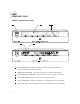
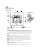
USER COMPONENT GUIDE CAV6.6 Controller-Front Panel 2 1 5 6 3 4 6 1 MAIN POWER SWITCH - Supplies power to the CAV6.6. The power switch for the CAV6.6 controller is "on" in the up position. 2 REMOVABLE COVER LENS - Covers the connections on the front of the CAV6.6 3 ROOM LED ON/OFF INDICATORS - Indicates when a room is on (green) or off (red) 4 ROOM LABEL WINDOW - Holds the selected room Label (included) 5 AUX A/V LINE INPUTS - Supports connection of a seventh A/V source to the CAV6.
USER COMPONENT GUIDE CAV6.6 Controller-Front Panel Front A/V AUX Connections The AUX Input is located to the right of the power switch on the front panel. Connect the Left, Right, and Video Input Connectors to the source component using quality RCA signal cables. The AUX IR jack adjacent to the line input accepts an IR Emitter with a 1/8” plug (e.g., Russound 845.1 IR emitter). The emitter’s other end attaches to the IR window of the component to control the auxiliary source.
USER COMPONENT GUIDE UNO-S2 Keypad 1 2 9 Command Keys 8 3 7 4 6 8 5 1 LCD PANEL - 12-character backlit display shows status of the room, source, volume, and more 2 MODE - “SYS-ON” indicates system on, “DND” shows when Do Not Disturb is active, “SHARED” indicates same source selected in multiple rooms, “PARTY”shows when Party Mode is enabled, and “MASTER” indicates the Master Keypad in Party Mode 3 SOURCE SELECT BUTTON - Scrolls through the sources directly connected to the CAV6.6.
USER COMPONENT GUIDE UNO-TS2 Touchscreen 1 2 10 3 9 4 8 5 7 6 1 IR RECEIVER - Receives IR signals and passes them to the controller and source equipment. Also used when operating the touchscreen by using the SRC2 remote 2 TOUCHSCREEN - Full color resistive touchscreen with multi-sound feedback. Screen can be programmed to go blank after a period of inactivity. Touching the screen anywhere reactivates it.
USER COMPONENT GUIDE UNO-S1 Keypad 1 102.5 2 6 3 5 4 1 LCD PANEL - 5-character backlit display shows source, volume and room status (messages scroll, then display first 5 characters of message) 2 SOURCE SELECT - Scrolls through the available sources. Press and hold brings up the USER MENU for loudness, bass, treble, etc. 3 VOLUME UP/DOWN BUTTONS - Raises and lowers the volume for the room 4 IR RECEIVER - Receives IR signals and passes them to the controller and source equipment.
USER COMPONENT GUIDE SRC2 Remote Control 11 1 POWER - Turns room or Local Source on and off. 2 RUSSOUND DEVICE BUTTON - Used for SRC2 control of zone keypad. 3 NUMBER BUTTONS - Buttons (0-9) for direct selection of channels or discs. 4 VOLUME UP/DOWN - Raises and lowers the volume for the room you are in, or for the selected Local Device. 5 CURSOR KEYS - Issues IR commands for source equipment, allowing movement through menus and program screens.
USER OPERATION UNO-S2 Keypad Button Functions Room On/Off is also used to enter the User Menu with a Press and release to turn on the UNO System Keypad. This also turns on the corre- press and hold action. (See next page for User Menu) sponding CAV6.6’s room, and any presets previously assigned will be activated, including settings for bass, volume, last source selected, etc. Press and release to turn off the UNO Volume Up/Down Buttons The room’s audio output is adjusted using .
USER OPERATION UNO-S2 User Menu - Setting Preferences The User Menu allows the user to adjust the audio properties and control functions of a particular room. The following keys are used to navigate and make changes while using the User Menu: To enter the User Menu, press and hold dur- ing normal operation. To exit the User Menu, press and release . Adjust feature setting (decrement). Go to next feature. Go to previous feature. View current feature setting.
USER OPERATION UNO-S1 Keypad Button Functions The UNO-S1 keypad operates in a similar panel. When a source is selected in more than manner as the UNO-S2 keypad. one room, the “SHARED” icon will appear on all UNO Keypads using that source. Room On/Off is also used to enter the User Menu with a press and Press and release to turn on the UNO hold action. (See next page for User Menu) System Keypad. This also turns on the corresponding CAV6.
USER OPERATION UNO-S1 User Menu - Setting Preferences The UNO-S1 User Menu allows the user to adjust the audio properties and control functions of a particular room. To enter or exit the User Menu, press and hold during normal operation. The following keys are used to navigate and make changes while using the User Menu: Press and hold to adjust feature setting (increment) Press and hold to adjust feature setting (decrement) Go to next feature. Go to previous feature. View current feature setting.
USER OPERATION UNO-TS2 Touchscreen Button Functions Room On/Off Source Select Button To turn on the room and the touchscreen, touch the UNO-TS2 screen anywhere, or press and release the power button. Any presets previously assigned will be activated, including settings for bass, volume, last source selected, etc. Press and release the power button to turn off the touchscreen, and to put the room into a standby state.
USER USER MENU SETTINGS UNO-TS2 - Setting Preferences The Options button on the UNO-TS2 home screen brings up room setting options and screen adjustments. (For more detailed information, consult the UNO-TS2 Instruction Manual) Features Turn On Volume - This sets the room’s default volume when the room is turned on. Party Mode - When in “PARTY MODE” the system is primarily controlled by a “MASTER” Keypad. Party Mode links all rooms to the same source which is selected by the Master Keypad room.
INSTALLER GETTING STARTED Unpacking the Components • Keep the original carton and packing materials for future shipment or storage. • Check for any visible signs of damage. If you encounter any concealed damage, consult your Russound dealer before proceeding to install the unit. • Retain the sales receipt as it establishes the duration of the limited warranty and provides information for insurance purposes.
INSTALLER COMPONENT GUIDE CAV6.
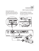
INSTALLER COMPONENT GUIDE CAV6.6 Controller-Rear Panel 1 21 20 2 20 19 3 18 17 4 16 15 5 14 13 12 11 6 10 9 8 1 ZONE 12VDC TRIGGER OUT - 12VDC 50ma is available whenever the corresponding zone is turned on 2 UNO KEYPAD PORTS - One UNO Keypad Port for each of the six CAV6.6 Zones 3 24VDC 2.5A INPUT - Provides power to the A-BUS READY SUB-ZONES when used with a 24VDC 2.5A power supply (e.g.
INSTALLER COMPONENT GUIDE CAV6.6 Controller-Rear Panel 10 SPEAKER OUTPUTS - Connect 8 Ohm speakers for each zone by using detachable color-coded modular snap connectors 11 AUDIO/VIDEO INPUTS - Six sets of Audio/Video Line Level input connections for CAV6.
INSTALLER COMPONENT GUIDE UNO Keypad-OS Update Port Software Update If a keypad update is released, it will be available online at www.russound.com through the Document Center, under RNET Systems. Before starting the update procedure, download updates to a PC and connect the correct programming cable from the PC to the OS update port on the front of the keypad.
INSTALLER COMPONENT GUIDE UNO Keypads-Rear Panel 2 NEWMARKET, NH U.S.A.
INSTALLER WIRING INSTRUCTIONS RJ-45 Connections The CAT-5 T568A wiring standard shown on the right is used for the RJ-45 terminations. Keypad Wiring For the UNO keypads, the following connections are used to terminate the CAT-5 wire to the 110 punchdown on the keypad: CAT-5 WIRE COLOR TYPE Brown . . . . . . . . . . . . . . . . . . . +12V Brown/White . . . . . . . . . . . . . . +12V Green . . . . . . . . . . . . . . . . . . Ground Green/White . . . . . . . . . . . . Status In Orange . . . . . . . . . . .
INSTALLER UNO-S2 KEYPAD-INSTALLATION UNO-S2 Keypad Connections CAT-5 Connection The UNO-S2 Keypad uses a 110-punchdown terminal to provide a simple installation and strong connection for CAT-5 cable’s eight conductors. Punchdown terminals require the use of a punchdown tool which has been provided with the keypad kit. Attach the CAT-5 cable to the 110 punchdown terminal on the UNO-S2 Keypad as shown, matching the conductor colors to the connection color guide.
INSTALLER UNO-S2 KEYPAD-INSTALLATION IR Receiver Connection The UNO-S2 keypad has an External IR Receiver In terminal for connecting an external IR receiver such as the Russound SaphIR 858, 862 Eye, or 860 Phantom. Use 2 twisted pair wire with KOREA Back of Russound 858 one pair connecting GND (GROUND) and IR (SIGNAL) and the other pair connecting ST (STATUS) and V+ (+12VDC). If the wire has a shield, connect it to ground at the UNO-S2 only.
INSTALLER UNO-S2 KEYPAD-INSTALLATION Keypad Location The best infrared remote performance is achieved with the keypad away from any direct sunlight, plasma TV, and low voltage lighting controls. Also consider convenience when choosing a location. Choose a place that is easily seen from the position where a person is most likely to be located. Check whether or not you can route the wire to the location you have chosen.
INSTALLER MAKING CONNECTIONS UNO System Keypad Port Connection The UNO System Keypad Ports are located on the back of the CAV6.6 in the top left corner. Connections made at the UNO Keypad Ports are made using CAT-5 T568A RJ-45 wire configuration. CAT-5 is color-coded for ease of installation. For a clean installation when wiring from an UNO System Keypad Port use an RJ-45 CAT-5 patch cable to connect from the keypad port to an RJ-45 Wall Plate (optional).
INSTALLER MAKING CONNECTIONS Source Audio/Video Input Connections The CAV6.6 supports up to six audio/video sources. The Source Inputs are located at the back panel. Connect each source output using quality RCA signal cables. Connect the Video, and the Left and Right Audio outputs from each source to the corresponding inputs on the CAV6.6 controller. Label each cable with the name of the selected source and the Source Audio/Video input number located on the CAV6.6.
INSTALLER MAKING CONNECTIONS Source Audio/Video Loop Output Connections The CAV6.6 has six buffered, fixed-level audio/video source loop outputs. This source loop configuration allows the CAV6.6 to pass source signals to another component, such as a home theater receiver or to another CAV6.6 for sharing 30 sources in a multiple controller system. The Source Loop Outputs are located directly to the right of the Source Audio/Video Inputs.
INSTALLER MAKING CONNECTIONS Speaker Connections The speakers are connected to the CAV6.6 using modular snap speaker connectors. Each of these color coded connectors is designated for the speaker set of a particular amplified zone. To avoid confusion, connect one zone speaker set at a time starting with Zone 1, taking care to keep zone and speaker wire identities straight. Note: An 8 Ohm minimum speaker is required for each amplified output.
INSTALLER MAKING CONNECTIONS ACC IR Connection The Accessory IR jack on the rear of the CAV6.6 allows control of any source equipment without that source being selected on the keypad. The connection for the ACC IR jack is made using an IR emitter with the 1/8’’ plug. The Russound 32 845.1 single IR emitter is recommended, or use an IR connecting block such as the Russound 857 which allows multiple units to be controlled through the ACC IR Port.
INSTALLER MAKING CONNECTIONS Zone Audio (to Amp) and Video Outputs The CAV6.6 has six Zone Audio/Video outputs. The Variable Audio outputs can be used if additional amplification is desired (e.g., Russound R235LS two-channel amplifier). The Zone Audio/Video Outputs are located slightly to the left of center on the rear of the CAV6.6. Use quality RCA signal cables to ensure a constant quality Audio signal. Video for the zone will be routed via the Video connection.
INSTALLER MAKING CONNECTIONS A-BUS Ready Sub-zone Connection A-BUS products can easily expand the CAV6.6 audio system by adding A-BUS Ready Sub-zones to the first four CAV6.6 zones. The A-BUS Ready Sub-zones are located on the back of the CAV6.6 at the bottom left corner. The A-BUS Ready Sub-zones are powered by a 24VDC power supply such as the A-PS. Use an RJ-45 CAT-5 T568A configuration patch cable to connect the A-BUS Ready Sub-zone 34 port to an RJ-45 wall plate (optional) for a clean installation.
INSTALLER MAKING CONNECTIONS 12VDC Trigger In/Out 12VDC Home Theater Trigger In This 12VDC Trigger input is used to control Power Management of the audio/video sources possibly being shared with a home theater system. When the source equipment is off and 12VDC is provided to the trigger, the sources will be turned on until it is removed. When the last zone on the CAV6.6 is turned off, 12VDC presence to the trigger input will prevent the sources from being turned off.
INSTALLER MAKING CONNECTIONS 12VDC Trigger In/Out 12VDC Page Trigger In When 12VDC is applied to the Page Trigger In, the system will page audio that is connected to the Page Audio Input and interrupt the video outputs with the page video signal. The Page Trigger In is located in the Page connection area of the CAV6.6 Controller. The connections for the trigger are made using a two-conductor cable with 1/8” male mini-plug jacks. The tip is positive (+) and sleeve is negative (-).
INSTALLER MAKING CONNECTIONS 12VDC Trigger In/Out 37
INSTALLER MAKING CONNECTIONS 12VDC Trigger In/Out Zone 12VDC Trigger Outputs Zone 12VDC Triggers are located directly under the UNO Keypad Ports. The 12VDC Trigger is engaged when the corresponding zone is turned on and disengaged when the zone is turned off. The trigger can be used to engage any 12VDC trigger device or component such as the 38 Russound R235LS amplifier. The connections for the trigger outputs are made using a two-conductor cable with 1/8” male mini-plug jacks at each end.
INSTALLER MAKING CONNECTIONS RNET Link In and Link Out - Multiple Controllers The RNET Link In and Link Out is used to connect two or more (up to 6) CAV6.6 or CAM6.6 controllers. The connection is made using a CAT-5 patch cable from the Link Out of the master controller and into the Link In of the next controller. Along with RNET data signals, the RNET Link In and Link Out jack passes the six source IR signals.
INSTALLER MAKING CONNECTIONS RNET Link In and Link Out - RNET-enabled Components The RNET Link In and Link Out is also used to connect the CAV6.6 to other Russound RNET-enabled products. The connection is made using a CAT-5 patch cable from the Link Out of the controller and into the Link In of the RNETenabled component. Another CAT-5 patch cable can be used to link out of that component and link into another RNET-enabled component in the system. RNET-enabled components fully integrate with CAV6.
INSTALLER MAKING CONNECTIONS RS-232 Interface The CAV6.6 supports RS-232 communication with various third-party automation systems through the RS-232 ports. These ports are also used for firmware updates, and for controller programming through the PC Power Tool software program. The two RS-232 com ports are located on the front and the back of the CAV6.6 and use a DB-9 cable connection.
INSTALLER MAKING CONNECTIONS Programming Center Keypad Port Connection The CAV6.6 can be programmed via keypad connection using CAT-5 and the T568A RJ-45 wire configuration. An UNO-S2 Keypad can be attached to the controller at the Programming Center Keypad Port Connection. The Programming Center Keypad Port is designed for use in local programming, specifi- 42 cally for learning IR commands directly into the IR receiver on the controller’s front panel. (see Learn IR flow chart on page 70). The CAV6.
INSTALLER INITIAL INSTALL TEST Before proceeding to the system programming section, it’s important to conduct an initial test to determine that the hardware components are working properly. 1. Connect the speaker wires from Zone #1 to the CAV6.6 Zone #1 speaker output connectors. 2. Connect an UNO keypad to Keypad Port #1 on the rear of the CAV6.6. 3. Connect a source to the Source #1 Input on the CAV6.6 using RCA A/V patch cables. 4. Plug a supplied 845.
INSTALLER PROGRAMMING System Programming Overview This manual includes items that are designed to assist in the programming process. Sample Configurations (Pages 80-91) A series of sample configurations are provided to showcase a variety of system designs and component options. Forms (pages 46-48) Three blank reproducible forms are included as planning tools when determining sources, settings and zone preferences.
INSTALLER PROGRAMMING System Programming Overview (cont’d) 2. Number of Sources (# of Sources/SOURCE SETUP) (Page 56) This procedure sets the number of sources used in the system. This prevents the user from selecting a source input that is not used. 3. Basic Setup (SOURCE SETUP) (Page 50) This procedure is mandatory to set up each source for keypad source control and is the cornerstone of the programming process. 4.
INSTALLER PROGRAMMING Source Information Form 46
INSTALLER PROGRAMMING Zone Information Form 47
INSTALLER PROGRAMMING Macro Editor Form 48
INSTALLER INSTALLATION MENU OVERVIEW There are three item types in the installation menu: Menu – Procedure – Feature – “Folder” that holds procedures and/or feature options. A series of steps to perform a guided operation, such as configuring a button. The actual settings that will change the system configuration. The following UNO-S1 and UNO-S2 buttons are used to navigate and make selections while using the installation menus. The UNO-TS2 does not support access to the Installation Menu.
INSTALLER INSTALLATION MENU The following items make up the Installation Menu: SOURCE SETUP (SrcSu) POWER MGT (PwMgt) ZONE SETUP (ZonSu) LEARN IR (LrnIR) CTRLR SETUP (CtlSu) MACRO EDITOR (MacEd) SYSTEM INFO (SInfo) SOURCE SETUP (SrcSu) Source Setup allows the system’s sources to be configured.
INSTALLER INSTALLATION MENU Basic Setup (cont’d.) ii. TEMPLATE TYP – (TType) Select the template type to define what type of source component is being used. (This will tell the CAV 6.6 how to configure the key commands and text for the source component if it is a learned source.) Procedure advances to USE NUM IR? (step 7). b. Selected: Unassigned (Unasg) The template for the selected source is cleared. (All key assignments and other source settings will be erased.
INSTALLER INSTALLATION MENU Key Config (cont’d.) 2. SOURCE NUM – (Src #) Select the source the key will be configured for. 3. SELECT A KEY – (SelKy) Using 4. KEY TYPE – (KeyTp) Either “Key Press,” “Key Hold” or “Both” will activate the command. 5. KEY NAME – (KeyNm) Name that appears on the keypad display when the command is activated. 6. COMMAND TYPE – (CmdTp) Select the type of source command (e.g., CD, TV, etc.). a. Selected: Learned IR – (LrnIR) i.
INSTALLER INSTALLATION MENU SOURCE NAMES (SrcNm) This procedure allows the installer to customize the source names for the sources attached to the CAV6.6. See Source Setup Menu on Page 50 and Source Names/Vol Trim - Flow Chart on page 64 1. SOURCE NUM – (Src #) Select the source number this name will be assigned to. 2. SOURCE NAME – (Name) Select the name. SOURCE NUM will reappear on the LCD panel; repeat the instructions for each source to be labeled.
INSTALLER INSTALLATION MENU Numeric IR (cont’d) a. Selected: Learned IR (LrnIR) i. LEARNED SRC – (LnSrc) Select the learned source bank to be assigned to the source component. Procedure advances to KEY FUNCTION (step 8) b. Selected: Unassigned (Unasg) The numeric IR Prefix command is cleared. Procedure advances to SUFFIX CMD (step 9) c. Selected: Default (Deflt) Default selects the same device type and device code previously setup in BASIC SETUP. Procedure advances to KEY FUNCTION (step 8) d.
INSTALLER INSTALLATION MENU Numeric IR (cont’d) i. MACRO (Macro) Macro loads a series of commands which are processed when activated. ii. MACRO ID – (MacID) Enter the macro ID number. Menu advances to SAVE CHANGES (step 13) e. All Other Selections: Procedure advances to DEVICE CODE (step 11) 11. DEVICE CODE – (DevCd) Source component code for IR control. 12. KEY FUNCTION – (KeyFn) Select a function (Enter, Play, etc.). 13. SAVE CHANGES? – (Save?) Select “yes” to save the changes.
INSTALLER INSTALLATION MENU Source Select Command (cont’d) e. All Other Selections: Procedure advances to DEVICE CODE (step 3) 3. DEVICE CODE – (DevCd) Source component code for IR control. 4. KEY FUNCTION – (KeyFn) Select a function (Play, Enter, etc.). 5. SAVE CHANGES? – (Save?) Select “yes” to save the changes. # OF SOURCES (#Srcs) At this field it is necessary to enter the number of sources used in the CAV6.6 system (1 to 6).
INSTALLER INSTALLATION MENU Zone Setup (cont’d) 5. PAGE ENABLE (PagEn) This feature is either disabled or enabled. It allows the option of receiving or blocking a page in a zone. If disabled, the page will not be sent to the zone. If enabled (default), the page will be sent to the zone. 6. PAGE VOLUME (PagVl) This feature allows the installer to adjust the Page Volume for the zone, from 0 (min) to 100 (max). CTRLR SETUP (CtlId) Controller Setup is the basic configuration of the controller.
INSTALLER INSTALLATION MENU Power Management (cont’d) one minute after that. This timeout is postponed for as long as the home theater trigger input has 12VDC present. See Installation Menu on Page 50 and Power Management - Flow Chart on page 69 1. SOURCE NUM – (Src #) Select the source number this feature will be configured for. 2.
INSTALLER INSTALLATION MENU Power Management (cont’d) 7. POWER OFF CMD – (OfCmd) Tells the controller to turn off the selected source equipment (by SOURCE NUMBER) when the last of the UNO System Keypads is turned off. If “no,” procedure advances to SAVE CHANGES (step 11) 8. COMMAND TYPE – (CmdTp) Select the type of source command (e.g., CD, TV, etc.). a. Selected: Learned IR (LrnIR) i. LEARNED SRC – (LnSrc) Choose Learned IR if the pre-programmed IR code library does not support the source component.
INSTALLER INSTALLATION MENU Learn IR (cont’d) 1. LEARNED SRC – (LnSrc) Select the source whose commands will be learned into the controller. 2. KEY FUNCTION – (KeyFn) Select the function to be learned or deleted. 3. LEARN/DELETE – (Ln/Dl) Select Learn IR Now or Delete IR. If Learn IR Now, a “USE REMOTE” prompt appears. Point the learning remote at the controller’s IR window. If Delete IR, procedure returns to LEARNED SRC (step 1) 4.
INSTALLER INSTALLATION MENU Macro Editor (cont’d) i. LEARNED SRC – (LnSrc) Select the learned source bank to be assigned to the source component. Procedure advances to KEY FUNCTION (step 6) b. Selected: Unassigned (Unasg) Selected command and subsequent commands are cleared. Procedure advances to COMMAND NUM (step 3) c. Selected: Default (Deflt) Default selects the same device type and device code previously setup in BASIC SETUP. Procedure advances to KEY FUNCTION (step 6) d. Selected: Macro: i.
INSTALLER SETUP MENU FLOW CHARTS Source Setup: Basic Setup 62
INSTALLER SETUP MENU FLOW CHARTS Source Setup: Key Configuration 63
INSTALLER SETUP MENU FLOW CHARTS Source Setup: Source Names/Volume Trim 64
INSTALLER SETUP MENU FLOW CHARTS Source Setup: Numeric IR 65
INSTALLER SETUP MENU FLOW CHARTS Source Setup: Source Select Command/# of Sources 66
INSTALLER SETUP MENU FLOW CHARTS Zone Setup 67
INSTALLER SETUP MENU FLOW CHARTS Controller Setup 68
INSTALLER SETUP MENU FLOW CHARTS Power Management 69
INSTALLER SETUP MENU FLOW CHARTS Learn IR 70
INSTALLER SETUP MENU FLOW CHARTS Macro Editor 71
INSTALLER SETUP MENU FLOW CHARTS System Info 72
INSTALLER KEYPAD DIAGNOSTIC MENU UNO Keypad Diagnostics Menu The Diagnostics Menu allows the installer to run a diagnostic check on the keypad and to verify the firmware version. The Diagnostics Menu also contains the update firmware procedure for updating the UNO-S1 and UNO-S2’s firmware. To access the Diagnostics Menu, press and hold the Setup button on the right side of the keypad until “DIAGNOSTICS” appears on the display. The menus are outlined in the diagram below.
INSTALLER IR DEVICE CODES Device Codes for TVs: Admiral Advent Aiko Akai Albatron America Action Anam AOC Apex Digital Audiovox Bell & Howell BenQ Bradford Broksonic Candle Carnivale Carver Celebrity Celera Changhong Citizen Clarion Comm’l Solutions Contec Craig Crosley Crown Curtis Mathes CXC Daewoo Dell Denon Dumont Durabrand Electroband Emerson Envision ESA Fisher Fujitsu Funai Futuretech Gateway GE Gibralter Go Video GoldStar Grunpy Haier Hallmark Harley Davidson Harman/Kardon Harvard Havermy Helios He
INSTALLER IR DEVICE CODES Device Codes for Cable: (cont’d) Starcom Supercable Supermax Torx Toshiba Tristar V2 Viewmaster Vision Vortex View Zenith 0003 0276 0883 0003 0000 0883 0883 0883 0883 0883 0000, 0525, 0899 Device Codes for Video Acc: ABS 1272 Alienware 1272 CyberPower 1272 D-Link 1554 Escient 1151, 1371, 1370, 1373, 1372 Gateway 1272 Hewlett Packard 1272, 1267 Howard Computers1272 iBUYPOWER 1272 LG 1415 Linksys 1365 Media Center PC 1272 Microsoft 1272 Mind 1272 Motorola 1363 Northgate 1272 Panas
INSTALLER IR DEVICE CODES Device Codes for VCRs: (cont’d) Pulsar Quasar Radio Shack Radix Randex RCA Realistic 0039 0035, 0162 0000 0037 0037 0060, 0240, 0042, 0149, 0880 0035, 0037, 0048, 0047, 0000, 0104 ReplayTV 0616 Runco 0039 Samsung 0045, 0240 Sanky 0048, 0039 Sansui 0000, 0067, 0209, 0041, 0479 Sanyo 0047, 0240, 0104 Scott 0184, 0045, 0121, 0043 Sears 0035, 0037, 0047, 0000, 0042, 0104 Sharp 0048 Shintom 0072 Shogun 0240 Singer 0072 Sonic Blue 0616 Sony 0035, 0032, 0033, 0000, 0636, 1972 STS 0042
INSTALLER IR DEVICE CODES Device Codes for Amp and Misc. Audio: Aiwa 0159 Altec Lansing 1485 Cambridge Sound.
SOURCE NAMES 78 UNO-S1 UNO-S2 Aux UNO-S1 UNO-S2 UNO-S1 UNO-S2 AUX CustomName3 DVD 3 DVD Player 3 Aux 1 AUX 1 CustomName4 FDoor Front Door Aux 2 AUX 2 CustomName5 Hers Her Music Blues Blues CustomName6 His His Music Cable Cable CustomName7 www.
SOURCE NAMES UNO-S1 UNO-S2 UNO-S1 UNO-S2 RepTV ReplayTV Tun 1 Tuner 1 Rock Rock Tun 2 Tuner 2 Sat Satellite Tun 3 Tuner 3 Sat 1 Satellite 1 TV TV Sat 2 Satellite 2 VCR VCR Sat 3 Satellite 3 VCR 1 VCR 1 SatRd Sat Radio VCR 2 VCR 2 Src 1 Source 1 <<>> Src 2 Source 2 XM 1 XM 1 Src 3 Source 3 XM 2 XM 2 Src 4 Source 4 XM 3 XM 3 Src 5 Source 5 XM XM Radio Src 6 Source 6 Src 7 Source 7 Src 8 Source 8 Spcl Special Tape Tape Tape1 Tape 1 Tape2
SAMPLE SYSTEM CONFIGURATION 1 Six Zones and Six Sources The configuration shows how the CAV6.6 distributes audio/video throughout the house using six UNO System Keypads and six audio/video source components. Source Components The configuration allows for any zone to select any one of the six source inputs. Keypads The configuration uses a single UNO-S2 Keypad per zone. Each keypad is connected to the CAV6.6’s Keypad Port using the RJ-45 T568A wiring configuration.
SAMPLE SYSTEM CONFIGURATION 1 Six Zones and Six Sources 81
SAMPLE SYSTEM CONFIGURATION 2 Integrate Multiple CAV6.6’s This configuration uses an additional CAV6.6 to add six additional amplified zones, controlled through UNO-S2 Keypads. The source components are connected to both CAV6.6s with RCA cables using the source in/loop out to interconnect the audio/video signals. RNET Link In and Link Out Multiple CAV6.6s can be integrated as the two shown in this configuration. An RJ-45 CAT-5 patch cable allows for communication between the two CAV6.6s.
SAMPLE SYSTEM CONFIGURATION 2 Integrate Multiple CAV6.
SAMPLE SYSTEM CONFIGURATION 3 Zone Keypad Expansion This configuration uses a SA-ZX3 Keypad Splitter hub to connect up to three UNO-S2 keypads to one CAV6.6 UNO keypad port. For clean installations, use RJ-45 CAT-5 patch cables with the T568A configuration. To connect from the SA-ZX3 to an RJ-45 wall plate (optional), use the patch cables to wire for Components List: 1 - CAV6.
SAMPLE SYSTEM CONFIGURATION 3 Zone Keypad Expansion 85
SAMPLE SYSTEM CONFIGURATION 4 A-BUS Ready Sub-Zone Addition Adding A-BUS allows sub-zoning of the audio distribution of the CAV6.6 system. This configuration demonstrates sub-zoning of the first zone through the use of an A-BUS expansion hub. Only the first four (1-4) CAV6.6 zones can be expanded using the same numbered (1-4) A-BUS Ready Sub-Zone ports. CAT-5 Connections The A-H2 Hub connects to the CAV6.6 A-BUS Ready Sub-Zone Port using RJ-45 CAT-5 cables. The cable connects from the CAV6.
SAMPLE SYSTEM CONFIGURATION 4 A-BUS Ready Sub-Zone Addition 1 2-ZONE, 1-SOURCE SURFACE MOUNT AUDIO HUB POWER 24VDC 2A 2 KEYPAD OUTPUTS BYPASS STATUS IR CONFIRM L R AUDIO IN 1 2 3 IR EMITTERS 4 EXPANSION INPUT DESIGNED IN USA MADE IN KOREA STATUS 12VDC 100mA NEWMARKET, NH U.S.A.
SAMPLE SYSTEM CONFIGURATION 5 Additional Amplification Additional amplification can be added to the CAV6.6 when more power or more speakers are desired. This configuration adds an external amplifier to the CAV6.6. The Zone Audio (To Amp) Outputs are variably controlled by the associated UNOS2 keypad and can be connected to an external amplifier. The figure shows an amplifier used in this manner. The configuration has five zones connected to an additional amplifier with one zone outputting to speakers.
SAMPLE SYSTEM CONFIGURATION 5 Additional Amplification 89
SAMPLE SYSTEM CONFIGURATION 6 Home Theater Home Theater systems can share sources with a CAV6.6 Controller to provide additional listening and viewing options. In this configuration, the Home Theater Receiver provides a 12VDC signal to the CAV6.6 at the Home Theater 12VDC In Port. The 12VDC signal tells the controller to leave any shared home theater source equipment powered when all CAV6.6 zones are off, temporarily bypassing the source power management feature. The 12VDC connected to the CAV6.
SAMPLE SYSTEM CONFIGURATION 6 Home Theater 91
INSTALLER KEY CODES TV (HDTV) 92 KEY FUNCTION UNO-S1 TV (HDTV) KEY FUNCTION UNO-S1 TV (HDTV) 1 1 Digit 1 Pause Pause Learned Only 2 2 Digit 2 Record Recrd Learned Only 3 3 Digit 3 Menu Menu Menu (Picture) 4 4 Digit 4 Menu Up MenuU Menu Up, Adjust Up 5 5 Digit 5 Menu Dn MenuD Menu Dn, Adjust Dn 6 6 Digit 6 Menu Left MenuL Menu Left 7 7 Digit 7 Menu Right MenuR Menu Right 8 8 Digit 8 Select Sel Menu Select 9 9 Digit 9 Exit Exit Exit, Cancel 0 0 Digi
INSTALLER KEY CODES TV (HDTV) KEY FUNCTION UNO-S1 TV (HDTV) KEY FUNCTION UNO-S1 TV (HDTV) Off Off Off, Power On/Off PIP Chan Up PIPCU PIP Channel Up 11 11 Learned Only PIP Chan Dn PIPCD PIP Channel Down 12 12 Learned Only Input 1 In 1 VID1,Video,TVp1 13 13 Learned Only Input 2 In 2 VID2,TVp2 14 14 Learned Only Input 3 In 3 VID3,TVp3 15 15 Learned Only Input 4 In 4 VID4,TVp4 16 16 Learned Only Input 5 In 5 VID5,AV1,VCR,BNC Bright Brght Learned Only Input 6 In 6
INSTALLER KEY CODES CABLE 94 KEY FUNCTION UNO-S1 CABLE KEY FUNCTION UNO-S1 CABLE 1 1 Digit 1 Pause Pause Pause 2 2 Digit 2 Record Recrd Record 3 3 Digit 3 Menu Menu Menu, Settings 4 4 Digit 4 Menu Up MenuU Menu Up 5 5 Digit 5 Menu Dn MenuD Menu Down 6 6 Digit 6 Menu Left MenuL Menu Left 7 7 Digit 7 Menu Right MenuR Menu Right 8 8 Digit 8 Select Sel Menu Select 9 9 Digit 9 Exit Exit Exit, Cancel 0 0 Digit 0 Display Displ Info, Display, OSD Volu
INSTALLER KEY CODES CABLE KEY FUNCTION UNO-S1 CABLE KEY FUNCTION UNO-S1 CABLE Off Off Off, Power On/Off PIP Chan Up PIPCU Learned Only 11 11 Learned Only PIP Chan Dn PIPCD Learned Only 12 12 Learned Only Input 1 In 1 A,VID1,Video,TVp1 13 13 Learned Only Input 2 In 2 B,VID2,TVp2 14 14 Learned Only Input 3 In 3 C,VID3,TVp3 15 15 Learned Only Input 4 In 4 VID4,TVp4 16 16 Learned Only Input 5 In 5 VID5,AV1,VCR,BNC Bright Brght Learned Only Input 6 In 6 VID6,AV2,V
INSTALLER KEY CODES VIDEO ACC 96 KEY FUNCTION UNO-S1 VIDEO ACC KEY FUNCTION UNO-S1 VIDEO ACC 1 1 Digit 1 Pause Pause Pause 2 2 Digit 2 Record Recrd Record 3 3 Digit 3 Menu Menu Menu, Home 4 4 Digit 4 Menu Up MenuU Menu Up 5 5 Digit 5 Menu Dn MenuD Menu Dn 6 6 Digit 6 Menu Left MenuL Menu Left 7 7 Digit 7 Menu Right MenuR Menu right 8 8 Digit 8 Select Sel Menu Select 9 9 Digit 9 Exit Exit Exit, Cancel, Go 0 0 Digit 0 Display Displ Info, Display,
INSTALLER KEY CODES VIDEO ACC KEY FUNCTION UNO-S1 VIDEO ACC KEY FUNCTION UNO-S1 VIDEO ACC Off Off Off, Power On/Off PIP Chan Up PIPCU PIP Channel Up 11 11 Learned Only PIP Chan Dn PIPCD PIP Channel Down 12 12 Learned Only Input 1 In 1 VID1,Video,TVp1 13 13 Learned Only Input 2 In 2 VID2,TVp2 14 14 Learned Only Input 3 In 3 VID3,TVp3 15 15 Learned Only Input 4 In 4 VID4,TVp4 16 16 Learned Only Input 5 In 5 VID5,AV1,VCR,BNC Bright Brght Learned Only Input 6 In 6
INSTALLER KEY CODES SAT/DSS 98 KEY FUNCTION UNO-S1 SAT/DSS KEY FUNCTION UNO-S1 SAT/DSS 1 1 Digit 1 Pause Pause Pause 2 2 Digit 2 Record Recrd Record 3 3 Digit 3 Menu Menu Menu (PVR, Tivo) 4 4 Digit 4 Menu Up MenuU Menu Up 5 5 Digit 5 Menu Dn MenuD Menu Down 6 6 Digit 6 Menu Left MenuL Menu Left 7 7 Digit 7 Menu Right MenuR Menu Right 8 8 Digit 8 Select Sel Menu Select 9 9 Digit 9 Exit Exit Exit, Cancel 0 0 Digit 0 Display Displ Info, Display,
INSTALLER KEY CODES SAT/DSS KEY FUNCTION UNO-S1 SAT/DSS KEY FUNCTION UNO-S1 SAT/DSS Off Off Off, Power On/Off PIP Chan Up PIPCU Learned Only 11 11 Learned Only PIP Chan Dn PIPCD Learned Only 12 12 Learned Only Input 1 In 1 VID1,Video,TVp1 13 13 Learned Only Input 2 In 2 VID2,TVp2 14 14 Learned Only Input 3 In 3 VID3,TVp3 15 15 Learned Only Input 4 In 4 VID4,TVp4 16 16 Learned Only Input 5 In 5 VID5,AV1,VCR,BNC Bright Brght Learned Only Input 6 In 6 VID6,AV2,V
INSTALLER KEY CODES VCR 100 KEY FUNCTION UNO-S1 VCR KEY FUNCTION UNO-S1 VCR 1 1 Digit 1 Pause Pause Pause 2 2 Digit 2 Record Recrd Record 3 3 Digit 3 Menu Menu Menu (PVR,Tivo) 4 4 Digit 4 Menu Up MenuU Menu Up 5 5 Digit 5 Menu Dn MenuD Menu Down 6 6 Digit 6 Menu Left MenuL Menu Left 7 7 Digit 7 Menu Right MenuR Menu Right 8 8 Digit 8 Select Sel Menu Select 9 9 Digit 9 Exit Exit Exit, Cancel 0 0 Digit 0 Display Displ Display, OSD, Info Volume U
INSTALLER KEY CODES VCR KEY FUNCTION UNO-S1 VCR KEY FUNCTION UNO-S1 VCR Off Off Off, Power On/Off PIP Chan Up PIPCU Learned Only 11 11 Learned Only PIP Chan Dn PIPCD Learned Only 12 12 Learned Only Input 1 In 1 VID1,Video,TVp1 13 13 Learned Only Input 2 In 2 VID2,TVp2 14 14 Learned Only Input 3 In 3 VID3,TVp3 15 15 Learned Only Input 4 In 4 VID4,TVp4 16 16 Learned Only Input 5 In 5 VID5,AV1,VCR,BNC Bright Brght Learned Only Input 6 In 6 VID6,AV2,VDP,DVD,DVI
INSTALLER KEY CODES LASER DISC 102 KEY FUNCTION UNO-S1 LASER DISC KEY FUNCTION UNO-S1 LASER DISC 1 1 Digit 1 Pause Pause Pause 2 2 Digit 2 Record Recrd Learned Only 3 3 Digit 3 Menu Menu Menu, Program 4 4 Digit 4 Menu Up MenuU Menu Up 5 5 5Digit 5 Menu Dn MenuD Menu Down 6 6 6Digit 6 Menu Left MenuL 7 7 Digit 7 Menu Right MenuR Menu Right 8 8 Digit 8 Select Sel Menu Select 9 9 Digit 9 Exit Exit Exit, Cancel 0 0 Digit 0 Display Displ Display, OSD, In
INSTALLER KEY CODES LASER DISC KEY FUNCTION UNO-S1 LASER DISC KEY FUNCTION UNO-S1 LASER DISC Off Off Off, Power On/Off PIP Chan Up PIPCU Learned Only 11 11 Learned Only PIP Chan Dn PIPCD Learned Only 12 12 Learned Only Input 1 In 1 VID1,Video,TVp1 13 13 Learned Only Input 2 In 2 VID2,TVp2 14 14 Learned Only Input 3 In 3 VID3,TVp3 15 15 Learned Only Input 4 In 4 VID4,TVp4 16 16 Learned Only Input 5 In 5 VID5,AV1,VCR,BNC Bright Brght Learned Only Input 6 In 6 V
INSTALLER KEY CODES DVD 104 KEY FUNCTION UNO-S1 DVD KEY FUNCTION UNO-S1 DVD 1 1 Digit 1, Traack 1 Pause Pause Pause 2 2 Digit 2, Track 2 Record Recrd Record 3 3 Digit 3, Track 3 Menu Menu Disk Menu 4 4 Digit 4, Track 4 Menu Up MenuU Menu Up 5 5 Digit 5, Track 5 Menu Dn MenuD Menu Dn 6 6 Digit 6, Track 6 Menu Left MenuL 7 7 Digit 7, Track 7 Menu Right MenuR Menu right 8 8 Digit 8,Track 8 Select Sel Menu Select 9 9 Digit 9, Track 9 Exit Exit Exit, Cancel, R
INSTALLER KEY CODES DVD KEY FUNCTION UNO-S1 DVD KEY FUNCTION UNO-S1 DVD Off Off Off, Power On/Off PIP Chan Up PIPCU Learned Only 11 11 Learned Only PIP Chan Dn PIPCD Learned Only 12 12 Learned Only Input 1 In 1 VID1,Video,TVp1 13 13 Learned Only Input 2 In 2 VID2,TVp2 14 14 Learned Only Input 3 In 3 VID3,TVp3 15 15 Learned Only Input 4 In 4 VID4,TVp4 16 16 Learned Only Input 5 In 5 VID5,AV1,VCR,BNC Bright Brght Learned Only Input 6 In 6 VID6,AV2,VDP,DVD,DVI
INSTALLER KEY CODES RECEIVER 106 KEY FUNCTION UNO-S1 RECEIVER KEY FUNCTION UNO-S1 RECEIVER 1 1 Digit 1 Pause Pause Pause 2 2 Digit 2 Record Recrd Record 3 3 Digit 3 Menu Menu Disk menu, Menu 4 4 Digit 4 Menu Up MenuU Menu Up, Adjust Up 5 5 Digit 5 Menu Dn MenuD Menu Dn, Adjust Dn 6 6 Digit 6 Menu Left MenuL Menu Left 7 7 Digit 7 Menu Right MenuR Menu Right 8 8 Digit 8 Select Sel Menu Select, Continue 9 9 Digit 9 Exit Exit Exit, Cancel 0 0 Digit 0
INSTALLER KEY CODES RECEIVER KEY FUNCTION UNO-S1 RECEIVER KEY FUNCTION UNO-S1 RECEIVER Off Off Off, Power On/Off PIP Chan Up PIPCU Learned Only 11 11 Learned Only PIP Chan Dn PIPCD Learned Only 12 12 Learned Only Input 1 In 1 CD 13 13 Learned Only Input 2 In 2 Tuner 14 14 Learned Only Input 3 In 3 DVD, LD 15 15 Learned Only Input 4 In 4 VCR, VID1 16 16 Learned Only Input 5 In 5 VID5,AV1,VCR,BNC Bright Brght Learned Only Input 6 In 6 TV, VID2 Dim Dim Learne
INSTALLER KEY CODES AMP/MISC AUDIO KEY FUNCTION UNO-S1 AMP/MISC AUDIO KEY FUNCTION UNO-S1 AMP/MISC AUDIO 108 1 1 Digit 1 Pause Pause Pause 2 2 Digit 2 Record Recrd Record 3 3 Digit 3 Menu Menu Menu, Program 4 4 Digit 4 Menu Up MenuU Menu Up, Adjust Up 5 5 Digit 5 Menu Dn MenuD Menu Dn, Adjust Dn 6 6 Digit 6 Menu Left MenuL Menu Left 7 7 Digit 7 Menu Right MenuR Menu Right 8 8 Digit 8 Select Sel Menu Select, Cont 9 9 Digit 9 Exit Exit Exit, Cancel 0 0
INSTALLER KEY CODES AMP/MISC AUDIO KEY FUNCTION UNO-S1 AMP/MISC AUDIO KEY FUNCTION UNO-S1 AMP/MISC AUDIO Off Off Off, Power On/Off PIP Chan Up PIPCU Learned Only 11 11 Learned Only PIP Chan Dn PIPCD Learned Only 12 12 Learned Only Input 1 In 1 CD 13 13 Learned Only Input 2 In 2 Tuner 14 14 Learned Only Input 3 In 3 DVD, LD 15 15 Learned Only Input 4 In 4 TAPE, MD 16 16 Learned Only Input 5 In 5 VCR, VID1 Bright Brght Learned Only Input 6 In 6 TV, VID2 Dim D
INSTALLER KEY CODES CD 110 KEY FUNCTION UNO-S1 CD KEY FUNCTION UNO-S1 CD 1 1 Digit 1, Track 1,Dsc1 Pause Pause Pause 2 2 Digit 2, Track 2,Dsc2 Record Recrd Record 3 3 Digit 3, Track 3,Dsc3 Menu Menu Disk, Edit 4 4 Digit 4, Track 4,Dsc4 Menu Up MenuU Menu Up 5 5 Digit 5, Track 5,Dsc5 Menu Dn MenuD Menu Down 6 6 Digit 6, Track 6,Dsc6 Menu Left MenuL 7 7 Digit 7, Track 7,Dsc7 Menu Right MenuR Menu Right 8 8 Digit 8,Track 8,Dsc8 Select Sel Menu Select, Cont 9 9
INSTALLER KEY CODES CD KEY FUNCTION UNO-S1 CD KEY FUNCTION UNO-S1 CD Off Off Off, Power On/Off PIP Chan Up PIPCU Learned Only 11 11 Learned Only PIP Chan Dn PIPCD Learned Only 12 12 Learned Only Input 1 In 1 CD 13 13 Learned Only Input 2 In 2 Tuner 14 14 Learned Only Input 3 In 3 DVD, LD 15 15 Learned Only Input 4 In 4 Tape, MD 16 16 Learned Only Input 5 In 5 VCR, VID1 Bright Brght Learned Only Input 6 In 6 TV, VID2 Dim Dim Learned Only Input 7 In 7 LD
INSTALLER KEY CODES HOME CONTROL 112 KEY FUNCTION UNO-S1 HOME CONTROL KEY FUNCTION UNO-S1 HOME CONTROL 1 1 Digit 1 Pause Pause Pause 2 2 Digit 2 Record Recrd Record 3 3 Digit 3 Menu Menu Menu 4 4 Digit 4 Menu Up MenuU Menu Up, Mode 5 5 Digit 5 Menu Dn MenuD Menu Dn, Timer 6 6 Digit 6 Menu Left MenuL Menu Left,Oscillate 7 7 Digit 7 Menu Right MenuR Menu Right,Speed 8 8 Digit 8 Select Sel Menu Select, Light 9 9 Digit 9 Exit Exit Exit, Cancel 0 0 Digi
INSTALLER KEY CODES HOME CONTROL KEY FUNCTION UNO-S1 HOME CONTROL KEY FUNCTION UNO-S1 HOME CONTROL Off Off Off, Power On/Off PIP Chan Up PIPCU Learned Only 11 11 Learned Only PIP Chan Dn PIPCD Learned Only 12 12 Learned Only Input 1 In 1 Source/Scene 1 13 13 Learned Only Input 2 In 2 Source/Scene 2 14 14 Learned Only Input 3 In 3 Source/Scene 3 15 15 Learned Only Input 4 In 4 Source/Scene 4 16 16 Learned Only Input 5 In 5 Source/Scene 5 Bright Brght Learned Only
TECHNICAL SPECIFICATION CAV6.6 Controller/Amplifier Dimensions: Weight: Power Supply: Fuse Rating: 17"W x 12"D x 3.5"H (43 x 30.5 x 9 cm) 18 lbs. (8.1 kg) 110 or 240 VAC 110V input; F3A H 250V US and Canada 240V input; F1.25A H 250V Europe Frequency Response: Watts per channel: Total Harmonic Distortion: Signal to Noise Ratio: A/V Source Inputs: 20Hz-20kHz +/- 0.5dB 20 Watts RMS x 12 into 8 Ohms 0.
WARRANTY & REPAIR The Russound CAV6.6 is fully guaranteed against all defects in materials and workmanship for two (2) years from the date of purchase. During this period, Russound will replace any defective parts and correct any defect in workmanship without charge for either parts or labor. For this warranty to apply, the unit must be installed and used according to its written instructions. If service is necessary, it must be performed by Russound.
CAV6.6 Six-Zone, Six-Source Audio-Video Controller Amplifier INSTRUCTION MANUAL Russound 5 Forbes Road, Newmarket, NH 03857 tel 603.659.5170 • fax 603.659.5388 e-mail: tech@russound.com www.russound.com Copyright ©2006 Russound® All rights reserved. All trademarks are property of their respective owners. A-BUS is a registered trademark of LeisureTech Electronics Pty Ltd Australia. Specifications subject to change without notice. Russound is not responsible for typographical errors or omissions.