CAA66 Multisource Multiroom Audio Controller/Amplifier Installation Manual
IMPORTANT SAFEGUARDS 10.Power Sources - The appliance should be connected to a power supply only of the type described in the operating instructions or as marked on the appliance. 11.Grounding or Polarization - Precaution should be taken so that the grounding or polarization means of an appliance is not defeated. WARNING: TO REDUCE THE RISK OF FIRE OR ELECTRIC SHOCK, DO NOT EXPOSE THIS APPLIANCE TO RAIN OR MOISTURE. CAUTION: TO REDUCE THE RISK OF ELECTRIC SHOCK, DO NOT REMOVE COVER.
TABLE OF CONTENTS USER SECTION Product Introduction ............................................................................................................5 Component Guide CAA66 Controller ................................................................................................................6 KP6 Keypad........................................................................................................................7 KPL Keypad ...........................................................
TABLE OF CONTENTS Common IR Input Connection .............................................................................................22 Speaker Connections ........................................................................................................23 Zone Fixed/Variable Audio Output .......................................................................................24 12VDC Mute Trigger In/Trigger Out ....................................................................................
INTRODUCTION Thank you for choosing the Russound® CAA66 controller amplifier to enhance your home with distributed audio. The CAA66 caters to homeowners who want more control over their multiroom systems with such capabilities as infrared (IR) tools to manage the system from anywhere in the house. More source inputs, simplified programming and user adjustable sound controls make listening to music throughout the home easier than ever.
COMPONENT GUIDE CAA66 FRONT PANEL The CAA66 front panel consists of a split molded piece with a removable bottom half. This bottom piece hides the Programming Center buttons. The power switch has a push on/push off action with a blue LED 1 2 “power on” indicator to the left which illuminates when the unit is on. The six zone LEDs light up amber when the zones are active.
COMPONENT GUIDE KP6 KEYPAD 1 8 2 3 7 4 6 5 KP6 Keypad 1 SOURCE NAME - Six clear windows with replaceable source name labels. Current source selected is backlit amber. 2 VOLUME UP - Raises the volume for the room/adjusts User Menu options. 3 VOLUME DOWN - Lowers the volume for the room/adjusts User Menu options. 4 POWER - Turns zone ON or OFF when pressed once. When OFF, press and hold will turn OFF all zones. Power button remains lit when OFF if any other zone in the system is ON.
COMPONENT GUIDE KPL KEYPAD 9 1 8 2 7 3 6 4 5 KPL Keypad 8 1 LCD PANEL - 5-character amber backlit display shows source name, volume and zone status. 2 VOLUME UP - Raises the volume for the room/adjust User Menu options. 3 VOLUME DOWN - Lowers the volume for the room/adjust User Menu options. 4 POWER - Turns zone ON or OFF when pressed once. When OFF, press and hold will turn OFF all zones.. Power button remains lit when OFF if any other zone in the system is ON.
COMPONENT GUIDE KPSC KEYPAD KPSC Source Control Keypad The KPSC keypad connects to a KP6 or KPL keypad to add source control and numeric capability. The amber backlit buttons provide primary source controls when pressed, such as stop, play, next, etc. When the Numeric button is pressed, it becomes backlit in red, and changes the buttons to numeric entry (0 - 9). Pressing the Numeric button also sends a Prefix command of “Disc.
COMPONENT GUIDE SRC1 SYSTEM REMOTE CONTROL 1 POWER - Turns on or off selected zone. 2 NUMERIC INPUT - Number buttons for direct input of frequency, channel, etc. 3 VOLUME UP/DOWN - Raises or lowers the volume in the zone. 4 MUTE - Mutes/unmutes zone audio output. 5 INFO - Displays current channel and program information. 6 CURSOR KEYS - Moves the cursor in the program guide and menu screens. 7 OK - Chooses the highlighted menu option. Performs “Enter” function for devices.
OPERATION USER OPTIONS SETTINGS KP6 Keypad User Options Mode Operation Source window blinks to indicate the option that is ready for adjustment Bass Treble Balance Turn On Volume Option setting level Press and hold Source button to enter or exit User Options Mode Press Volume Up or Down buttons to adjust setting Blue LED will blink to indicate Loudness is ready for adjustment KP6 User Options Mode The User Options Mode allows the user to adjust the audio properties of a particular zone.
OPERATION USER OPTIONS SETTINGS KPL Keypad User Options Mode Operation Press and hold Source button to enter or exit User Options Mode Press Volume Up or Down buttons to adjust setting Press Source button to select option Blue LED will blink to indicate Loudness is ready for adjustment KPL User Options Mode Options and Settings The User Options Mode allows the user to adjust the audio properties of a particular zone.
INSTALLER GETTING STARTED Unpacking the System Components • Keep the original carton and packing materials for future shipment or storage. System Installation Considerations There are several factors to consider before installing the Russound CAA66 system: • Check for any visible signs of damage. If you encounter any concealed damage, consult your Russound dealer before proceeding to install the unit.
INSTALLER WIRING INSTRUCTIONS RJ-45 Connections The CAT-5 T568A wiring standard shown on the right is used for the RJ-45 terminations. Keypad Wiring For the KP6 or KPL keypad, the following connections are used to terminate the CAT-5 wire to the 110 punchdown on the keypad: CAT-5 WIRE COLOR TYPE Brown. . . . . . . . . . . . . . . . . . . . . +12V • Confirm ahead of time that you can drill an outlet hole easily and in an unobtrusive spot to connect wires with the CAA66.
INSTALLER COMPONENT GUIDE Controller Front Panel Removal Front Panel Removal The CAA66 front panel removable bottom half hides the Programming Center. It is important to follow the proper removal process to remove the panel without damage. To remove the panel, you must be able to access the slots located underneath the front of the controller. Place a flat screwdriver blade in the bottom slot on the left and right between the cover and the controller. Twist the blade to loosen the cover from its catches.
INSTALLER COMPONENT GUIDE Controller Back Panel 2 1 15 16 4 3 14 5 13 6 12 11 7 10 8 9 1 CONTROLLER LINK IN AND LINK OUT - Links multiple CAA66 controllers and peripherals. 2 RS-232 INTERFACE - The RS-232 Interface allows the zones to be controlled by PC or other devices that have an RS-232 Interface, allows for firmware updates and programming. 3 CPU UPDATE SWITCH - For firmware updates. 4 KEYPAD PORTS - One KP6/KPL Keypad Port for each of the six CAA66 Zones.
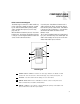
INSTALLER COMPONENT GUIDE Keypad Update Port The KPSC 12-pin header and the update jumper for the KP6 (and KPL) are located on the right side of the keypad when facing front. These are covered when a trim plate is installed. Note: The update pins on the KP6 are accessed from the side when the keypad is not installed. 3 1 OS UPDATE/RUN JUMPER -The pins are jumpered when performing a firmware update on the keypad. The jumper is removed during normal operation.
INSTALLER COMPONENT GUIDE Keypad Rear Panel and Installation CAT-5 to KP6/KPL Connection The KP6/KPL keypad uses a 110punchdown terminal on the back panel to provide simple installation and a strong connection for CAT-5 cable’s eight conductors. Punchdown terminals require the use of a punchdown tool. Attach the CAT-5 cable to the 110-punchdown terminal on the KP6 keypad as shown, matching the conductor colors to the connection color guide.
INSTALLER MAKING CONNECTIONS Keypad Port Connection The Keypad Ports are located on the back of the CAA66 in the top left of center. Connections at the Keypad Ports are made with RJ45 connectors using T568A CAT-5 wire configuration. For a clean installation when wiring from a Keypad Port, use an RJ45 CAT-5 patch cable to connect from the keypad port to an RJ-45 wall plate (optional). Using the same RJ45 T568A CAT-5 wiring configuration, use CAT-5 from the RJ45 wall plate to the keypad.
INSTALLER MAKING CONNECTIONS Source Audio and IR Connections Source Audio Connections The CAA66 supports up to six audio sources. The Source Inputs are located on the back panel. Connect each source using quality RCA signal cables. Connect the Left and Right Audio outputs from each source to the corresponding inputs on the CAA66 controller. Label each cable with the name of the selected source and the Source Audio input number located on the CAA66.
INSTALLER MAKING CONNECTIONS RNET Source Audio Input Connections RNET Source Audio Connections The CAA66 supports source control of Russound RNET components (ST2 Smart Tuner, SMS3 Smart Media Server) through the Controller Link ports via SRC1 remote control commands but provides no feedback to keypads. RNET Link In/Out Connections The RNET components are linked to the controller and each other using RJ45 patch cables connected to the Link In and Link Out ports.
INSTALLER MAKING CONNECTIONS Common IR Connection Common IR Connections The Common IR jack on the rear of the CAA66 allows control of any source equipment without that source being selected on the keypad. The connection for the Com IR jack is made using an IR emitter with a 1/8’’ plug or IR link cable. 22 The Russound 845.1 single IR emitter is recommended, or use an IR connecting block such as the Russound 857 which allows multiple units to be controlled through the COM IR Port.
INSTALLER MAKING CONNECTIONS Speaker Connections The speakers are connected to the CAA66 using modular snap connectors. Each of these colorcoded connectors is designated for the speaker set of a particular amplified zone. To avoid confusion, connect one zone speaker set at a time starting with Zone 1, taking care to keep zone and speaker wire identities straight. Note: An 8 Ohm minimum speaker is required for each amplified output.
INSTALLER MAKING CONNECTIONS Zone Fixed/Variable Audio Outputs Zone Fixed/Variable Audio Output The CAA66 has two line Audio outputs, on Zone 1 and Zone 2. Each of these zone audio output connections features a stereo line out RCA connection plus a switch to allow for either a fixed or a variable line level output. When set to Variable, the keypad volume level affects this output. In the Fixed position, the keypad volume level will not change the output level.
INSTALLER MAKING CONNECTIONS 12VDC Mute Trigger In/System Trigger Out 12VDC Mute Trigger In When 12VDC is applied to the Mute In, the system will fully mute all zones in the system. The connections for the trigger are made using a twoconductor cable with 1/8” male mini-plug jacks. The tip is positive (+) and sleeve is negative (-). This allows for the connection of an external paging or muting device.
INSTALLER MAKING CONNECTIONS Controller Link In and Link Out Controller Link In/Out The Controller Link In and Link Out can be used to connect up to six CAA66 controllers. The connection is made using a CAT-5 patch cable from the Link Out of the master CAA66 and into the Link In of the next controller. Along with data signals, the Controller Link In and Link Out jack passes the six source IR signals.
INSTALLER MAKING CONNECTIONS RS-232 Interface The CAA66 supports RS-232 communication with various third party automation systems or PC for control and firmware updates of the controller. The RS-232 com port is located on the back of the CAA66 and uses a DB-9 cable connection. For firmware updates, be sure the CPU Update switch next to the the RS232 interface is set in the “Update” position. For RS-232 protocol, firmware updates and the backup PC application, see the Document Center at www.russound.com.
INSTALLER INITIAL HARDWARE INSTALL TEST Before proceeding to the system programming section, it’s important to conduct an initial test to determine that the hardware components are working properly. 1. Connect the speaker wires from Zone #1 to the CAA66 Zone #1 speaker output connectors. 2. Connect a keypad (KP6, KPL) to Keypad Port #1 on the rear of the CAA66. 3. Connect a source to the Source #1 Input on the CAA66 using RCA Audio patch cables. 4. Plug an 845.
INSTALLER PROGRAMMING OVERVIEW Programming Center The CAA66 and its connected sources are configured through the Programming Center, located on the front of the CAA66 behind the removable lower panel. The LEDs are dual purpose with different colors to indicate different modes. The CAA66 has two main programming modes: Controller Setup Mode and Source Setup Mode.
INSTALLER PROGRAMMING OVERVIEW 30
INSTALLER PROGRAMMING OVERVIEW 31
INSTALLER PROGRAMMING OVERVIEW 32
INSTALLER PROGRAMMING OVERVIEW 33
INSTALLER PROGRAMMING OVERVIEW 34
INSTALLER PROGRAMMING OVERVIEW 35
INSTALLER PROGRAMMING OVERVIEW 36
INSTALLER PROGRAMMING OVERVIEW 37
INSTALLER PROGRAMMING OVERVIEW 38
INSTALLER PROGRAMMING OVERVIEW 39
INSTALLER CAA66 SOURCE SETUP FLOW CHART 40
INSTALLER KPL SETUP AND DIAGNOSTIC MENUS KPL Setup Menu The KPL Setup menu is used to choose source names, check the version number and perform a Factory Initialization of the CAA66 controller. The menu is outlined in the diagram to the right. To access the Setup Menu, press and release the Setup button on the right side of the keypad until “SrcNm” (source names) appears on the display.
REFERENCE SOURCE NAMES - KPL KEYPAD 42 5-Character Display Description 5-Character Display Description 5-Character Display Description Aux Auxiliary DSS DSS Receiver MSvr1 Media Server 1 Aux 1 Auxiliary 1 DSS 1 DSS 1 MSvr2 Media Server 2 Aux 2 Auxiliary 2 DSS 2 DSS 2 MSvr3 Media Server 3 Blues Blues DSS 3 DSS 3 MiniD Mini Disk Cable Cable DVDCh DVD Changer Mood Mood Music Cbl 1 Cable 1 DVDC1 DVD Changer1 MornM MorningMusic Cbl 2 Cable 2 DVDC2 DVD Changer2 MP3
REFERENCE SOURCE NAMES - KPL/KP6 KEYPADS 5-Character Display Description 5-Character Display Description KP6 Labels Src 4 Source 4 XM 3 XM 3 AM/FM Src 5 Source 5 XMRad XM Radio AM/FM 1 Src 6 Source 6 AM/FM 2 Src 7 Source 7 CABLE Src 8 Source 8 CD Specl Special CD1 Tape Tape CD2 Tape1 Tape 1 DVD Tape2 Tape 2 DVR TiVo TIVO iPod Tuner Tuner RADIO Tun 1 Tuner 1 SAT Tun 2 Tuner 2 SERVER 1 Tun 3 Tuner 3 SERVER 2 TV TV SERVER 3 VCR VCR SIRIUS VCR 1 VCR 1
REFERENCE UEI LIBRARY IR CODES Device Codes for TVs: AOC Admiral Advent Aiko Aiwa Akai Alaron America Action Ampro Anam Apex Digital Audiovox Baysonic Belcor Bell & Howell Bradford Brockwood Broksonic CXC Candle Carnivale Carver Celebrity Changhong Cineral Citizen Concerto Contec Craig Crosley Crown Curtis Mathes Daewoo Daytron Denon Dumont Dwin Electroband Emerson Envision Fisher Fujitsu Funai Futuretech GE Gibralter GoldStar Gradiente Grunpy Hallmark Harley Davidson Harman/Kardon Harvard Havermy Hitachi
REFERENCE UEI LIBRARY IR CODES Philips Pioneer Princeton Samsung Sensory Science Sharp Sony 1818, 1061 1010 0113, 0295 1190, 1204 1126 1010 0850 Device Codes for SAT/DSS: AlphaStar Chaparral Crossdigital Echostar Expressvu GE GOI General Instrument HTS Hitachi Hughes Net. Sys.
REFERENCE UEI LIBRARY IR CODES Realistic Sony Technics 0203 0201, 0193 0204 Device Codes for DVD Players: Aiwa Apex Digital Blue Parade Broksonic Daewoo Denon Emerson Enterprise Fisher GE Go Video Gradiente Harman/Kardon Hitachi Hiteker JBL JVC Kenwood Konka Koss Lasonic Magnavox Malata Marantz Microsoft Mitsubishi Onkyo Oritron Panasonic Philips Pioneer Princeton Proscan RCA Rowa Sampo Samsung Sansui Sanyo Sharp Sherwood Sony Sylvania Technics Techwood Theta Digital Toshiba Urban Concepts Yamaha Zenith
TECHNICAL SPECIFICATIONS CAA66 Controller/Amplifier Dimensions: Weight: Power Supply: Fuse Rating: 17"W x 11.5"D x 3.9"H (43 x 29.2 x 10 cm) 17 lbs. 12.5 oz. (8 kg) VAC 100-120 @3A or 220-240V @1.25A 50-60Hz 110V input; F3.0A H 250V US and Canada 240V input; T1.25A H 250V Europe Frequency Response: Watts per channel: Total Harmonic Distortion: Signal to Noise Ratio: Audio Source Inputs: Input Impedance: Audio Zone Outputs: 20Hz-20kHz +0/-2.5dB 20W RMS into 8 ohms <0.10% >90.
WARRANTY & REPAIR The Russound CAA66 is fully guaranteed against all defects in materials and workmanship for two (2) years from the date of purchase. During this period, Russound will replace any defective parts and correct any defect in workmanship without charge for either parts or labor. For this warranty to apply, the unit must be installed and used according to its written instructions. If service is necessary, it must be performed by Russound.
NOTES 49
NOTES 50
NOTES 51
CAA66 Multisource Multiroom Audio Controller/Amplifier Installation Manual Russound, Inc. 5 Forbes Road, Newmarket, NH 03857 tel 603.659.5170 • fax 603.659.5388 e-mail: tech@russound.com www.russound.com Copyright © 2005 Russound® All rights reserved. All trademarks are property of their respective owners. 28-1199 Rev.