CAM6.6 Six-Zone, Six-Source Controller CAM6.
IMPORTANT SAFEGUARDS 9. Heat - The appliance should be situated away from heat sources such as radiators, heat registers, stoves, or other appliances (including amplifiers) that produce heat. 10.Power Sources - The appliance should be connected to a power supply only of the type described in the operating instructions or as marked on the appliance. WARNING: TO REDUCE THE RISK OF FIRE OR ELECTRIC SHOCK, DO NOT EXPOSE THIS APPLIANCE TO RAIN OR MOISTURE. 11.
TABLE OF CONTENTS USER SECTION Product Introduction ............................................................................................................................5 Component Guide CAM6.6 Controller ..............................................................................................................................6 UNO-S1 Keypad..................................................................................................................................7 UNO-S2 Keypad ............
TABLE OF CONTENTS Speaker Connections ........................................................................................................................36 Zone Fixed/Variable Audio Output ......................................................................................................37 12VDC Home Theater Trigger In/Out..................................................................................................38 12VDC Mute Trigger In/Out ....................................................
PRODUCT INTRODUCTION Thank you for choosing the Russound® CAM6.6 multisource, multizone controller to enhance your home with distributed audio. This controller’s state-of-the-art features and components blend seamlessly with your unique lifestyle and preferences. Besides distributing and controlling six audio sources to six rooms (zones) using RNET® keypads, your CAM6.6 offers many features that increase your enjoyment of living. Here are several that you may find particularly beneficial.
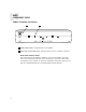
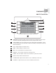
USER COMPONENT GUIDE CAM6.6 Controller-Front Panel 1 2 1 MAIN POWER SWITCH - Supplies power to the CAM6.6 2 ROOM LED ON/OFF INDICATORS - Indicates when a room is on (green) or off (red) Main Power and Zone Status The power switch for the CAM6.6 controller is “on” in the up position. Any active room (1-6) is indicated on the front of the controller by a green LED, which shows red when the room is inactive.
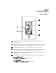
USER COMPONENT GUIDE UNO-S1 Keypad 1 102.5 2 6 3 5 4 1 LCD PANEL - 5-character backlit display shows status of the room, source, volume, and more 2 SOURCE SELECT BUTTON - Scrolls through the sources directly connected to the CAM6.6. Press and hold brings up the USER MENU for loudness, bass, treble, etc. 3 VOLUME UP/DOWN BUTTONS - Raises and lowers the volume for the room 4 IR RECEIVER - Receives IR signals and passes them to the controller and source equipment.
USER COMPONENT GUIDE UNO-S2 Keypad 1 Command Keys 7 CD PLAYER 1 2 6 3 5 8 4 1 LCD PANEL - 12-character backlit display shows status of the room, source, volume, and more 2 SOURCE SELECT BUTTON - Scrolls through the sources directly connected to the CAM6.6. Press and hold brings up the USER MENU for loudness, bass, treble, etc. 3 VOLUME UP/DOWN BUTTONS - Raises and lowers the volume for the room 4 IR RECEIVER - Receives IR signals and passes them to the controller and source equipment.
USER COMPONENT GUIDE UNO-TS2 Touchscreen 1 2 10 3 9 4 8 5 7 6 1 IR RECEIVER - Receives IR signals and passes them to the controller and source equipment. Also used when operating the touchscreen by using the SRC2 remote 2 TOUCHSCREEN - Full color resistive touchscreen with multi-sound feedback. Screen can be programmed to go blank after a period of inactivity. Touching the screen anywhere reactivates it.
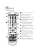
USER COMPONENT GUIDE SRC2 Remote Control 11 1 POWER - Turns room or Local Source on and off. 2 RUSSOUND DEVICE BUTTON - Used for SRC2 control of zone keypad. 3 NUMBER BUTTONS - Buttons (0-9) for direct selection of channels or discs. 4 VOLUME UP/DOWN - Raises and lowers the volume for the room you are in, or for the selected Local Device. 5 CURSOR KEYS - Issues IR commands for source equipment, allowing movement through menus and program screens.
USER OPERATION UNO-S1 Keypad Button Function Room On/Off Press and release used to enter the User Menu with a press and to turn on the UNO System Keypad. This also turns on the corresponding CAM6.6’s room, and any presets previously assigned will be activated, including settings for bass, volume, last source selected, etc. Press and release to turn off the UNO System Keypad. This will also put the corresponding CAM6.6’s room into a standby state. hold action.
USER USER MENU SETTINGS UNO-S1 User Menu Operation The User Menu allows the user to adjust the audio properties and control functions of a particular room. To enter or exit the User Menu, press and hold during normal operation. The following keys are used to navigate and make changes while using the User Menu: Press and hold to adjust feature setting (increment) Press and hold to adjust feature setting (decrement) Go to next feature. Go to previous feature. View current feature setting.
USER OPERATION UNO-S2 Keypad Button Function Room On/Off Press and release used to enter the User Menu with a press and to turn on the UNO System Keypad. This also turns on the corresponding CAM6.6’s room, and any presets previously assigned will be activated, including set- hold action. (See next page for User Menu) Volume Up/Down Buttons The room’s audio output is adjusted using . tings for bass, volume, last source selected, etc.
USER USER MENU SETTINGS UNO-S2 User Menu Operation The User Menu allows the user to adjust the audio properties and control functions of a particular room. The following keys are used to navigate and make changes while using the User Menu: To enter the User Menu, press and hold during normal operation. To exit the User Menu, press and release . Adjust feature setting (decrement). Go to next feature. Go to previous feature. View current feature setting.
USER OPERATION UNO-TS2 Touchscreen Button Function Room On/Off Source Select Button To turn on the room and the touchscreen, touch the UNO-TS2 screen anywhere, or press and release the power button. Any presets previously assigned will be activated, including settings for bass, volume, last source selected, etc. Press and release the power button to turn off the touchscreen, and to put the room into a standby state.
USER USER MENU SETTINGS UNO-TS2 - Setting Preferences The Options button on the home screen brings up room setting options and screen adjustments. (For more detailed information, consult the UNO-TS2 Instruction Manual) Features Turn On Volume - This sets the room’s default volume when the room is turned on. Party Mode - When in “PARTY MODE” the system is primarily controlled by a “MASTER” Keypad. Party Mode links all rooms to the same source which is selected by the Master Keypad room.
USER INTERNAL SOURCE - AM/FM TUNER UNO-S1 Keypad Control UNO-S1 Keypad Control of Tuner through frequencies. The frequency will scroll Selecting the tuner twice on the keypad then stop and display the On the UNO-S1 keypad, press to select the station’s first 5 characters. AM/FM tuner by choosing the tuner’s preas- Setting a Memory Preset signed source number (1). The SRC2 remote control is used to set memory Selecting the desired frequency presets for all six banks.
USER INTERNAL SOURCE - AM/FM TUNER UNO-S2 Keypad Control UNO-S2 Keypad Control of Tuner of six called banks, and there are six banks. Selecting the tuner Each preset and each bank can be given a cus- On the UNO-S2 keypad, press to select the tom name of your choice. AM/FM tuner by choosing the tuner’s preas- To select a bank, press and hold signed source number (1). up or for bank for bank down. The bank’s name will be temporarily displayed on the UNO-S2.
USER INTERNAL SOURCE - AM/FM TUNER UNO-S2 Keypad Control 1 6 92.
USER INTERNAL SOURCE - AM/FM TUNER UNO-TS2 Touchscreen Control UNO-TS2 Control of Tuner Selecting the tuner On the UNO-TS2 touchscreen home page, press the named source button to select the AM/FM tuner. Selecting a Bank From the “1 of 3” tuner screen, select the bank by scrolling using the forward/back arrow next to the bank name. The bank name shows in the window. There are six available banks that store up to six presets each.
USER INTERNAL SOURCE - AM/FM TUNER UNO-TS2 Touchscreen Control Banks and Memory Presets Tuner 1 Example of Bank and Preset screen for Russound Tuner Dad’s Music WBZ 1030 102.5 Class 107.1 MHz FM WEEI 850 89.7 NHPR 105.7 Oldies 1 of 3 Numeric Station/Channel Selection Tuner 1 Example of numeric station selection screen for Russound Tuner 2 of 3 AM/FM Tuner Advanced Features 107.
USER INTERNAL SOURCE - AM/FM TUNER SRC2 Remote Control SRC2 Control of Tuner Frequency Scan Selecting the tuner To scan, press and hold then release To select the tuner, push to toggle through . The tuner scans through tuned stations with a 5-second sources and choose the source number preassigned preview before moving to the next station. To end to the AM/FM tuner (1), or use the UNO numeric scanning, press source inputs at the bottom of the SRC2.
USER INTERNAL SOURCE - AM/FM TUNER SRC2 Remote Control RUSSOUND SELECTION - “R” must be the selected source for control of the CAM6.6 and any connected components. Select “R” before sending SRC2 remote commands. 1 POWER - Power managed by CAM6.
INSTALLER SECTION Getting Started Includes an installation overview, including tools needed and connection tips. Component Guides Reviews front and back panel features of the CAM6.6 controller and the UNO keypads. Keypad Installation Explains UNO keypad installation and wiring. Making Connections Details front and back panel connections of the controller and the keypads. System Programming Overview Outlines the programming planning process.
INSTALLER GETTING STARTED Unpacking the System Components • Keep the original carton and packing materials for future shipment or storage. • Check for any visible signs of damage. If you encounter any concealed damage, consult your Russound dealer before proceeding to install the unit. • Retain the sales receipt as it establishes the duration of the limited warranty and provides information for insurance purposes.
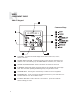
INSTALLER COMPONENT GUIDE CAM6.6 Controller-Rear Panel 1 2 3 4 5 6 7 8 9 10 11 CAM6.6 19 20 26 18 17 16 15 14 13 12 1 RNET LINK IN AND LINK OUT - Links multiple CAM6.6’s, also links future Russound components that are RNET compatible 2 RS-232 INTERFACE - The RS-232 Interface allows the zones to be controlled by PC or other devices that have an RS-232 Interface. The RS-232 Interface also allows for firmware updates and programming.
INSTALLER COMPONENT GUIDE CAM6.6 Controller-Rear Panel 10 OPTIONAL INTERNAL SOURCE - Factory installed optional internal source, AM/FM radio module 11 AC 240V-AC 110V Switch - Switches A/C input voltage between 110VAC and 240VAC 12 AC 120/240 INPUT - Grounded 3-terminal plug detachable power cord connection for the CAM6.6 13 FUSE HOLDER - Holds a replaceable fuse for A/C input connection 110VAC operation - F 3A H 250V, 240VAC operation; T 1.
INSTALLER COMPONENT GUIDE UNO Keypad Update Port Software Update If a keypad update is released, it will be available online at www.russound.com through the Document Center, under RNET Systems. Before starting the update procedure, download updates to a PC and connect the correct programming cable from the PC to the OS update port on the front of the keypad.
INSTALLER COMPONENT GUIDE UNO Keypad-Rear Panel 2 NEWMARKET, NH U.S.A.
INSTALLER WIRING INSTRUCTIONS Wire Length To determine the amount of CAT-5 wire required for the system installation, first decide how many keypads will be used, then determine the distance between each intended keypad location to the intended CAM6.6 location. The maximum recommended wire run length is 250 feet for each UNO keypad. • Make sure that the entire wire path between keypads and CAM6.6 is clear and not obstructed by a floor ceiling joist, or masonry wall which can’t be drilled through.
INSTALLER WIRING INSTRUCTIONS IR Receiver Connection The UNO-S2 keypad has an External IR Receiver IN terminal for connecting an external IR receiver such as the Russound SaphIR 858, 862 Eye, or 860 Phantom. Use 2 twisted pair wire with KOREA Back of Russound 858 one pair connecting GND (GROUND) and IR (SIGNAL) and the other pair connecting ST (STATUS) and V+ (+12VDC). If the wire has a shield, connect it to ground at the UNO-S2 only.
INSTALLER UNO KEYPAD INSTALLATION Keypad Location The best infrared remote performance is achieved with the keypad away from any direct sunlight, plasma TV, and low voltage lighting controls. Also consider convenience when choosing a location. Choose a place that is easily seen from the position where a person is most likely to be located. Check whether or not you can route the wire to the location you have chosen.
INSTALLER MAKING CONNECTIONS UNO Keypad Port Connection The UNO System Keypad Ports are located on the back of the CAM6.6 in the top left of center. Connections made at the UNO Keypad Ports are made using CAT-5 T568A RJ-45 wire configuration. CAT-5 is color-coded for ease of installation. For a clean installation when wiring from an UNO System Keypad Port use an RJ-45 CAT-5 patch cable to connect from the keypad port to an RJ-45 Wall Plate (optional).
INSTALLER MAKING CONNECTIONS Source Audio and IR Input Connections Source Audio Connections The CAM6.6 supports up to six audio sources. The Source Inputs are located at the back panel. For the CAM6.6 (no internal source installed), the switch next to Source 1 input must be set to “Input.” Connect each source output using quality RCA signal cables. Connect the Left and Right Audio outputs from each source to the corresponding inputs on the CAM6.6 controller.
INSTALLER MAKING CONNECTIONS Common IR Connection Common IR Connections The Common IR jack on the rear of the CAM6.6 allows control of any source equipment without that source being selected on the keypad. The connection for the COM IR jack is made using an IR emitter with a 1/8’’ plug. The Russound 845.1 single IR emitter is recommended, or use an IR connecting block such as the Russound 857 which allows multiple units to be controlled through the COM IR Port. CAM6.6 CAM6.
INSTALLER MAKING CONNECTIONS Speaker Connections The speakers are connected to the CAM6.6 using modular snap connectors. Each of these color-coded connectors is designated for the speaker set of a particular amplified zone. To avoid confusion, connect one zone speaker set at a time starting with Zone 1, taking care to keep zone and speaker wire identities straight. Note: An 8 Ohm minimum speaker is required for each amplified output.
INSTALLER MAKING CONNECTIONS Zone Fixed/Variable Audio Outputs The CAM6.6 has two Zone Audio outputs, on Zone 1 and Zone 2. Each of these zone audio output connections features a stereo line out RCA connection plus a switch to allow for either a fixed or a variable line level output. When set to Variable, the keypad volume level affects this output. In the Fixed position, the keypad volume level will not change the output level.
INSTALLER MAKING CONNECTIONS 12VDC Home Theater Trigger In/Out 12VDC Home Theater Trigger In This 12VDC Trigger input is used to control Power Management of the audio sources possibly being shared with a home theater system. When the last zone on the CAM6.6 is turned off, 12VDC presence to the trigger input will prevent the sources that are on from being turned off. The connections for the trigger are made using a twoconductor cable with 1/8” male mini-plug.
INSTALLER MAKING CONNECTIONS 12VDC Mute Trigger In/Out 12VDC Mute Trigger In When 12VDC is applied to the Mute Trigger In, the system will fully mute any source that is connected to the Source Audio Input. The connections for the trigger are made using a two-conductor cable with 1/8” male mini-plug jacks. The tip is positive (+) and sleeve is negative (-). This allows for the connection of an external paging or muting device. The CAM6.
INSTALLER MAKING CONNECTIONS RNET Link In and Link Out The RNET Link In and Link Out can be used to connect two to six CAM6.6 or CAV6.6 controllers. The connection is made using a CAT-5 patch cable from the Link Out of the master CAM6.6 and into the Link In of the next controller. Along with RNET data signals, the RNET Link In and Link Out jack passes the six source IR signals. These are only for source-specific IR remote repeating, not codes initiated from the controller’s internal IR library.
INSTALLER MAKING CONNECTIONS RS-232 Interface The CAM6.6 supports RS-232 communication with various third party automation systems or PC for programming of the controller. The RS-232 com port is located on the back of the CAM6.6 and uses a DB-9 cable connection. For RS-232 protocol and the backup PC application, go to www.russound.com, Document Center. Under RNET Systems, look under the heading for Technical Documents. CAM6.
INSTALLER MAKING CONNECTIONS Optional Internal Source - AM/FM Tuner Antennas AM Antenna FM Antenna Connect the included loop antenna for AM reception to the Optional Internal Source panel, attaching the GND (ground) and AM ends to the appropriately marked connections. Attach the included FM antenna for FM reception to the Optional Internal Source panel by pushing the F-type quick-connect termination of the antenna onto the FM connection. CAM6.
INSTALLER MAKING CONNECTIONS Optional Internal Source - AM/FM Tuner Antennas Connecting an Alternate Outdoor Antenna for AM/FM The diagram below depicts a suggested installation option of an alternate outdoor FM antenna and AM antenna. For best performance for AM reception, it is recommended to use an external outdoor or atticmounted long wire antenna for best performance for AM reception. Use a 75-ohm to 300-ohm balun at the AM connection on the tuner, and attach the 75-ohm coax cable to the balun.
INSTALLER MAKING CONNECTIONS Grounding Outdoor Antennas Antenna Lead In Wire Electric Service Equipment Grounding Conductors Ground Clamps Grounding an Outdoor Antenna If the tuner is used with an outdoor antenna, the antenna must be grounded against static charges and voltage surges. Consult the instructions that came with the antenna or contact the antenna manufacturer for proper installation instructions.
INSTALLER INITIAL INSTALL TEST Before proceeding to the system programming section, it’s important to conduct an initial test to determine that the hardware components are working properly. 1. Connect the speaker wires from Zone #3 to the CAM6.6 Zone #3 speaker output connectors. 2. Connect an UNO keypad to Keypad Port #3 on the rear of the CAM6.6. 3. Connect a source to the Source #3 Input on the CAM6.6 using RCA Audio patch cables. 4. Plug a supplied 845.
INSTALLER SYSTEM PROGRAMMING OVERVIEW This manual includes items that are designed to assist in the programming process. Forms (Pages 106-108) Three blank reproducible forms are included as planning tools when determining sources, settings and zone preferences. The Source and Zone Information forms and the Macro Editor form should be completed before programming and referred to during the installation menu process. This speeds up programming time and reduces missed or incorrect entries.
INSTALLER SYSTEM PROGRAMMING OVERVIEW 3. Basic Setup (SOURCE SETUP) (Pages 51-53) This procedure is mandatory to set up each source for keypad source control and is the cornerstone of the programming process. 4. Peripheral Setup (Pages 49-51) (FOR OPTIONAL INTERNAL SOURCE) This procedure provides setup and naming procedures for the tuner. It includes assigning a custom name to a memory preset or bank, and choosing a region for AM/FM operation (US or Euro). 5.
INSTALLER INSTALLATION MENU OVERVIEW There are three item types in the installation menu: Menu – Procedure – Feature – “Folder” that holds procedures and/or feature options. A series of steps to perform a guided operation, such as configuring a button. The actual settings that will change the system configuration. The following UNO-S1 and UNO-S2 buttons are used to navigate and make selections while using the installation menus. The UNO-TS2 does not support access to the Installation Menu.
INSTALLER INSTALLATION MENU The following items make up the Installation Menu: PERIPH SETUP (PerSu) SOURCE SETUP (SrcSu) CTRLR SETUP (CtlSu) POWER MGT (PwMgt) MACRO EDITOR (MacEd) ZONE SETUP (ZonSu) LEARN IR (LrnIR) SYSTEM INFO (SInfo) PERIPH SETUP (PerSu) Not Avail” shows on the keypad. Note: For CAM6.6, Peripheral Setup is not applicable. “N Peripheral Setup allows the CAM6.6’s optional internal source to be configured.
INSTALLER INSTALLATION MENU 2. BANK NAME – (BnkNm) Use the volume up/down keys to select a character and left/right keys to change a character position. A blinking cursor indicates placement of the character being entered. Names can be from 1 to 5 characters in length. If adding names from 6-12 characters, it is suggested you use an optional UNO-S2 keypad. CONTROLLR ID (CtlId) This procedure is used to identify the controller(s) that the tuner will respond to. See Periph Setup Flow Chart on page 65 1.
INSTALLER INSTALLATION MENU SYSTEM INFO (SInfo) System Info shows the tuner’s manufacturing build properties. See Periph Setup - Flow Chart on page 65 BUILD TIME (BTime) BUILD DATE (BDate) VERSION (Ver) 1. BUILD TIME (BTime) Displays the firmware Build Time of the tuner. 2. BUILD DATE (BDate) Displays the firmware Build Date of the tuner. 3. VERSION (Ver) Displays the firmware version of the tuner. SOURCE SETUP (SrcSu) Source Setup allows the system’s sources to be configured.
INSTALLER INSTALLATION MENU 52 2. SOURCE NAME – (Name) Select the name for the source (e.g., DVD, Aux 2, Jazz, etc.). 3. COMMAND TYPE – (CmdTp) Select the type of command template (e.g., CD, TV, etc.). Selecting the command type template will tell the CAM 6.6 how to configure the key’s command and text for the source component. a. Selected: Learned IR (LrnIR) Choose Learned IR if the pre-programmed IR code library does not support the source component. i.
INSTALLER INSTALLATION MENU 9. AUTO PLAY? – (AtoPl) “Yes” tells the CAM6.6 to issue a PLAY command whenever the source is selected for listening. This option is skipped if the source type (COMMAND TYPE) chosen does not have a PLAY command associated with it. 10. SAVE CHANGES? – (Save?) Select “yes” to save changes. Procedure returns to SOURCE NUM to allow configuration of another source. KEY CONFIG (KeyCf) Key Configuration defines zone-specific key functions for each source. See Key Config.
INSTALLER INSTALLATION MENU i. MACRO (Macro) Macro loads a series of commands which are processed when activated. ii. MACRO ID – (MacID) Enter the macro ID number. Menu advances to SAVE CHANGES (step 9) e. All Other Selections: Procedure advances to DEVICE CODE (step 7) 7. DEVICE CODE – (DevCd) Enter source component code number listed in this manual’s Reference section. 8. KEY FUNCTION – (KeyFn) Select a function for the button. 9. SAVE CHANGES? – (Save?) Select “yes” to save changes.
INSTALLER INSTALLATION MENU 1. SOURCE NUM – (Src #) Select the source number this function will be configured for. 2. USE NUM IR? – (NumIR) Tells the system whether the source component has numeric scrolling, such as 100-disc CD player. A selection of “no” disables Numeric IR and advances to SAVE CHANGES 3. HIGHEST NUM – (High#) Enter the highest possible number; for example, the 100-disc CD player would have a max number of 100. 4. NUMERIC TEXT – (NmTxt) Select Numeric descriptive text. 5.
INSTALLER INSTALLATION MENU 9. SUFFIX CMD – (Sufix) Tells the system whether a command will be issued after the selection of the numerical value (e.g., 1, 2 Enter). If “no,” procedure advances to SAVE CHANGES (step 13) 10. COMMAND TYPE – (CmdTp) Select the type of source command (e.g., CD, TV, etc.). a. Selected: Learned IR (LrnIR) i. LEARNED SRC – (LnSrc) Choose Learned IR if the pre-programmed IR code library does not support the source component.
INSTALLER INSTALLATION MENU 2. COMMAND TYPE – (CmdTp) a. Selected: Learned IR (LrnIR) i. LEARNED SRC – (LnSrc) Select the type of source command (e.g., CD, TV, etc.). Choose Learned IR if the pre-programmed IR code library does not support the source component. Select the learned source bank to be assigned to the source component. Procedure advances to KEY FUNCTION (step 4) b. Selected: Unassigned (Unasg) The source select command is cleared. Procedure advances to SAVE CHANGES (step 5) c.
INSTALLER INSTALLATION MENU ZONE SETUP (ZonSu) NOTE: This procedure should be performed using the keypad installed in the zone to be configured. See Zone Setup - Flow Chart on page 71 Zone Setup allows the installer to adjust properties of the UNO Keypad controlled CAM6.6 zone. This series of menus allows the system’s zones to be configured for these properties: ZON VOL TRIM (ZonVT) SYSON ENABLE (SysOn) MASTER ENABL (MstEn) MUTE ENABLE (MutEn) PARTY ENABLE (PtyEn) 1.
INSTALLER INSTALLATION MENU 2. FACTORY INIT (FInit) WARNING: This procedure returns the controller to its original settings - use with discretion. Factory Initialization allows the installer to erase all programmed settings and returns the settings to the factory default settings. All settings including source equipment IR commands will need to be reentered. An “Are you sure?” prompt and a “no” response allows the installer to cancel the reset; a “yes” at the prompt will load factory/default settings.
INSTALLER INSTALLATION MENU c. Selected: Default (Deflt) Default selects the same device type and device code previously setup in BASIC SETUP. Procedure advances to KEY FUNCTION (step 5) d. Selected: Macro: (Macro) i. MACRO (Macro) (To build macros, see Macro Editor page 62) ii. MACRO ID – (MacID) e. All Other Selections: Enter the macro ID number. Menu advances to POWER OFF CMD (step 6) Procedure advances to DEVICE CODE (step 4) 4. DEVICE CODE – (DevCd) Source component code for IR control. 5.
INSTALLER INSTALLATION MENU e. All Other Selections: Procedure advances to DEVICE CODE (step 8) 8. DEVICE CODE – (DevCd) Source component code for IR control. 9. KEY FUNCTION (f) – (KeyFn) Select Keypad function. 10. SAVE CHANGES? (f) – (Save?) Select “yes” to save the changes. LEARN IR (LrnIR) This procedure allows IR commands to be learned into the system and be centrally stored in the main controller to let the system access the same IR codes that operate the source equipment.
INSTALLER INSTALLATION MENU MACRO EDITOR (MacEd) This procedure is used to create a sequence of commands that are launched with one key touch or other event. Up to 132 macros can be created for the system, and each macro can contain up to 10 commands including other macros and delays. See Macro Editor - Flow Chart on page 75 1. MACRO ID – (MacID) Number of Macro up to 132 including any previously named macros. 2. MACRO NAME – (MacNm) Name of Macro (optional). 3.
INSTALLER INSTALLATION MENU 5. DEVICE CODE – (DevCd) Source component code for IR control. 6. KEY FUNCTION – (KeyFn) Select a function (Play, etc.). SYSTEM INFO (SInfo) System Info allows the installer to view the controller’s manufacturing build properties. See System Info - Flow Chart on page 76 #CONTROLLERS (#Ctls) BUILD TIME (BTime) BUILD DATE (BDate) VERSION (Ver) 1. #CONTROLLERS (#Ctls) Displays the number of CAM6.6 controllers in the system. 2.
INSTALLER SETUP MENU FLOW CHARTS 64
INSTALLER SETUP MENU FLOW CHARTS 65
INSTALLER SETUP MENU FLOW CHARTS 66
INSTALLER SETUP MENU FLOW CHARTS 67
INSTALLER SETUP MENU FLOW CHARTS 68
INSTALLER SETUP MENU FLOW CHARTS 69
INSTALLER SETUP MENU FLOW CHARTS 70
INSTALLER SETUP MENU FLOW CHARTS 71
INSTALLER SETUP MENU FLOW CHARTS 72
INSTALLER SETUP MENU FLOW CHARTS 73
INSTALLER SETUP MENU FLOW CHARTS 74
INSTALLER SETUP MENU FLOW CHARTS 75
INSTALLER SETUP MENU FLOW CHARTS 76
INSTALLER KEYPAD DIAGNOSTIC MENU UNO Keypad Diagnostics Menu The Diagnostics Menu allows the installer to run a diagnostic check on the keypad and to verify the firmware version. The Diagnostics Menu also contains the update firmware procedure for updating the UNO-S1 and UNO-S2’s firmware. To access the Diagnostics Menu, press and hold the Setup button on the right side of the keypad until “DIAGNOSTICS” appears on the display. The menus are outlined in the diagram below.
INSTALLER IR DEVICE CODES Device Codes for TVs: Admiral Advent Aiko Akai Albatron America Action Anam AOC Apex Digital Audiovox Bell & Howell BenQ Bradford Broksonic Candle Carnivale Carver Celebrity Celera Changhong Citizen Clarion Comm’l Solutions Contec Craig Crosley Crown Curtis Mathes CXC Daewoo Dell Denon Dumont Durabrand Electroband Emerson Envision ESA Fisher Fujitsu Funai Futuretech Gateway GE Gibralter Go Video GoldStar Grunpy Haier Hallmark Harley Davidson Harman/Kardon Harvard Havermy Helios He
INSTALLER IR DEVICE CODES Device Codes for Cable: (cont’d) Starcom Supercable Supermax Torx Toshiba Tristar V2 Viewmaster Vision Vortex View Zenith 0003 0276 0883 0003 0000 0883 0883 0883 0883 0883 0000, 0525, 0899 Device Codes for Video Acc: ABS 1272 Alienware 1272 CyberPower 1272 D-Link 1554 Escient 1151, 1371, 1370, 1373, 1372 Gateway 1272 Hewlett Packard 1272, 1267 Howard Computers1272 iBUYPOWER 1272 LG 1415 Linksys 1365 Media Center PC 1272 Microsoft 1272 Mind 1272 Motorola 1363 Northgate 1272 Panas
INSTALLER IR DEVICE CODES Device Codes for VCRs: (cont’d) Pulsar Quasar Radio Shack Radix Randex RCA Realistic 0039 0035, 0162 0000 0037 0037 0060, 0240, 0042, 0149, 0880 0035, 0037, 0048, 0047, 0000, 0104 ReplayTV 0616 Runco 0039 Samsung 0045, 0240 Sanky 0048, 0039 Sansui 0000, 0067, 0209, 0041, 0479 Sanyo 0047, 0240, 0104 Scott 0184, 0045, 0121, 0043 Sears 0035, 0037, 0047, 0000, 0042, 0104 Sharp 0048 Shintom 0072 Shogun 0240 Singer 0072 Sonic Blue 0616 Sony 0035, 0032, 0033, 0000, 0636, 1972 STS 0042
INSTALLER IR DEVICE CODES Device Codes for Amp and Misc. Audio: Aiwa 0159 Altec Lansing 1485 Cambridge Sound.
INSTALLER KEY CODES TV (HDTV) 82 KEY FUNCTION UNO-S1 TV (HDTV) KEY FUNCTION UNO-S1 TV (HDTV) 1 1 Digit 1 Pause Pause Learned Only 2 2 Digit 2 Record Recrd Learned Only 3 3 Digit 3 Menu Menu Menu (Picture) 4 4 Digit 4 Menu Up MenuU Menu Up, Adjust Up 5 5 Digit 5 Menu Dn MenuD Menu Dn, Adjust Dn 6 6 Digit 6 Menu Left MenuL Menu Left 7 7 Digit 7 Menu Right MenuR Menu Right 8 8 Digit 8 Select Sel Menu Select 9 9 Digit 9 Exit Exit Exit, Cancel 0 0 Digi
INSTALLER KEY CODES TV (HDTV) KEY FUNCTION UNO-S1 TV (HDTV) KEY FUNCTION UNO-S1 TV (HDTV) Off Off Off, Power On/Off PIP Chan Up PIPCU PIP Channel Up 11 11 Learned Only PIP Chan Dn PIPCD PIP Channel Down 12 12 Learned Only Input 1 In 1 VID1,Video,TVp1 13 13 Learned Only Input 2 In 2 VID2,TVp2 14 14 Learned Only Input 3 In 3 VID3,TVp3 15 15 Learned Only Input 4 In 4 VID4,TVp4 16 16 Learned Only Input 5 In 5 VID5,AV1,VCR,BNC Bright Brght Learned Only Input 6 In 6
INSTALLER KEY CODES CABLE 84 KEY FUNCTION UNO-S1 CABLE KEY FUNCTION UNO-S1 CABLE 1 1 Digit 1 Pause Pause Pause 2 2 Digit 2 Record Recrd Record 3 3 Digit 3 Menu Menu Menu, Settings 4 4 Digit 4 Menu Up MenuU Menu Up 5 5 Digit 5 Menu Dn MenuD Menu Down 6 6 Digit 6 Menu Left MenuL Menu Left 7 7 Digit 7 Menu Right MenuR Menu Right 8 8 Digit 8 Select Sel Menu Select 9 9 Digit 9 Exit Exit Exit, Cancel 0 0 Digit 0 Display Displ Info, Display, OSD Volu
INSTALLER KEY CODES CABLE KEY FUNCTION UNO-S1 CABLE KEY FUNCTION UNO-S1 CABLE Off Off Off, Power On/Off PIP Chan Up PIPCU Learned Only 11 11 Learned Only PIP Chan Dn PIPCD Learned Only 12 12 Learned Only Input 1 In 1 A,VID1,Video,TVp1 13 13 Learned Only Input 2 In 2 B,VID2,TVp2 14 14 Learned Only Input 3 In 3 C,VID3,TVp3 15 15 Learned Only Input 4 In 4 VID4,TVp4 16 16 Learned Only Input 5 In 5 VID5,AV1,VCR,BNC Bright Brght Learned Only Input 6 In 6 VID6,AV2,V
INSTALLER KEY CODES VIDEO ACC 86 KEY FUNCTION UNO-S1 VIDEO ACC KEY FUNCTION UNO-S1 VIDEO ACC 1 1 Digit 1 Pause Pause Pause 2 2 Digit 2 Record Recrd Record 3 3 Digit 3 Menu Menu Menu, Home 4 4 Digit 4 Menu Up MenuU Menu Up 5 5 Digit 5 Menu Dn MenuD Menu Dn 6 6 Digit 6 Menu Left MenuL Menu Left 7 7 Digit 7 Menu Right MenuR Menu right 8 8 Digit 8 Select Sel Menu Select 9 9 Digit 9 Exit Exit Exit, Cancel, Go 0 0 Digit 0 Display Displ Info, Display,
INSTALLER KEY CODES VIDEO ACC KEY FUNCTION UNO-S1 VIDEO ACC KEY FUNCTION UNO-S1 VIDEO ACC Off Off Off, Power On/Off PIP Chan Up PIPCU PIP Channel Up 11 11 Learned Only PIP Chan Dn PIPCD PIP Channel Down 12 12 Learned Only Input 1 In 1 VID1,Video,TVp1 13 13 Learned Only Input 2 In 2 VID2,TVp2 14 14 Learned Only Input 3 In 3 VID3,TVp3 15 15 Learned Only Input 4 In 4 VID4,TVp4 16 16 Learned Only Input 5 In 5 VID5,AV1,VCR,BNC Bright Brght Learned Only Input 6 In 6
INSTALLER KEY CODES SAT/DSS 88 KEY FUNCTION UNO-S1 SAT/DSS KEY FUNCTION UNO-S1 SAT/DSS 1 1 Digit 1 Pause Pause Pause 2 2 Digit 2 Record Recrd Record 3 3 Digit 3 Menu Menu Menu (PVR, Tivo) 4 4 Digit 4 Menu Up MenuU Menu Up 5 5 Digit 5 Menu Dn MenuD Menu Down 6 6 Digit 6 Menu Left MenuL Menu Left 7 7 Digit 7 Menu Right MenuR Menu Right 8 8 Digit 8 Select Sel Menu Select 9 9 Digit 9 Exit Exit Exit, Cancel 0 0 Digit 0 Display Displ Info, Display,
INSTALLER KEY CODES SAT/DSS KEY FUNCTION UNO-S1 SAT/DSS KEY FUNCTION UNO-S1 SAT/DSS Off Off Off, Power On/Off PIP Chan Up PIPCU Learned Only 11 11 Learned Only PIP Chan Dn PIPCD Learned Only 12 12 Learned Only Input 1 In 1 VID1,Video,TVp1 13 13 Learned Only Input 2 In 2 VID2,TVp2 14 14 Learned Only Input 3 In 3 VID3,TVp3 15 15 Learned Only Input 4 In 4 VID4,TVp4 16 16 Learned Only Input 5 In 5 VID5,AV1,VCR,BNC Bright Brght Learned Only Input 6 In 6 VID6,AV2,V
INSTALLER KEY CODES VCR 90 KEY FUNCTION UNO-S1 VCR KEY FUNCTION UNO-S1 VCR 1 1 Digit 1 Pause Pause Pause 2 2 Digit 2 Record Recrd Record 3 3 Digit 3 Menu Menu Menu (PVR,Tivo) 4 4 Digit 4 Menu Up MenuU Menu Up 5 5 Digit 5 Menu Dn MenuD Menu Down 6 6 Digit 6 Menu Left MenuL Menu Left 7 7 Digit 7 Menu Right MenuR Menu Right 8 8 Digit 8 Select Sel Menu Select 9 9 Digit 9 Exit Exit Exit, Cancel 0 0 Digit 0 Display Displ Display, OSD, Info Volume Up
INSTALLER KEY CODES VCR KEY FUNCTION UNO-S1 VCR KEY FUNCTION UNO-S1 VCR Off Off Off, Power On/Off PIP Chan Up PIPCU Learned Only 11 11 Learned Only PIP Chan Dn PIPCD Learned Only 12 12 Learned Only Input 1 In 1 VID1,Video,TVp1 13 13 Learned Only Input 2 In 2 VID2,TVp2 14 14 Learned Only Input 3 In 3 VID3,TVp3 15 15 Learned Only Input 4 In 4 VID4,TVp4 16 16 Learned Only Input 5 In 5 VID5,AV1,VCR,BNC Bright Brght Learned Only Input 6 In 6 VID6,AV2,VDP,DVD,DVI
INSTALLER KEY CODES LASER DISC 92 KEY FUNCTION UNO-S1 LASER DISC KEY FUNCTION UNO-S1 LASER DISC 1 1 Digit 1 Pause Pause Pause 2 2 Digit 2 Record Recrd Learned Only 3 3 Digit 3 Menu Menu Menu, Program 4 4 Digit 4 Menu Up MenuU Menu Up 5 5 5Digit 5 Menu Dn MenuD Menu Down 6 6 6Digit 6 Menu Left MenuL 7 7 Digit 7 Menu Right MenuR Menu Right 8 8 Digit 8 Select Sel Menu Select 9 9 Digit 9 Exit Exit Exit, Cancel 0 0 Digit 0 Display Displ Display, OSD, Inf
INSTALLER KEY CODES LASER DISC KEY FUNCTION UNO-S1 LASER DISC KEY FUNCTION UNO-S1 LASER DISC Off Off Off, Power On/Off PIP Chan Up PIPCU Learned Only 11 11 Learned Only PIP Chan Dn PIPCD Learned Only 12 12 Learned Only Input 1 In 1 VID1,Video,TVp1 13 13 Learned Only Input 2 In 2 VID2,TVp2 14 14 Learned Only Input 3 In 3 VID3,TVp3 15 15 Learned Only Input 4 In 4 VID4,TVp4 16 16 Learned Only Input 5 In 5 VID5,AV1,VCR,BNC Bright Brght Learned Only Input 6 In 6 V
INSTALLER KEY CODES DVD 94 KEY FUNCTION UNO-S1 DVD KEY FUNCTION UNO-S1 DVD 1 1 Digit 1, Traack 1 Pause Pause Pause 2 2 Digit 2, Track 2 Record Recrd Record 3 3 Digit 3, Track 3 Menu Menu Disk Menu 4 4 Digit 4, Track 4 Menu Up MenuU Menu Up 5 5 Digit 5, Track 5 Menu Dn MenuD Menu Dn 6 6 Digit 6, Track 6 Menu Left MenuL 7 7 Digit 7, Track 7 Menu Right MenuR Menu right 8 8 Digit 8,Track 8 Select Sel Menu Select 9 9 Digit 9, Track 9 Exit Exit Exit, Cancel, Re
INSTALLER KEY CODES DVD KEY FUNCTION UNO-S1 DVD KEY FUNCTION UNO-S1 DVD Off Off Off, Power On/Off PIP Chan Up PIPCU Learned Only 11 11 Learned Only PIP Chan Dn PIPCD Learned Only 12 12 Learned Only Input 1 In 1 VID1,Video,TVp1 13 13 Learned Only Input 2 In 2 VID2,TVp2 14 14 Learned Only Input 3 In 3 VID3,TVp3 15 15 Learned Only Input 4 In 4 VID4,TVp4 16 16 Learned Only Input 5 In 5 VID5,AV1,VCR,BNC Bright Brght Learned Only Input 6 In 6 VID6,AV2,VDP,DVD,DVI
INSTALLER KEY CODES RECEIVER 96 KEY FUNCTION UNO-S1 RECEIVER KEY FUNCTION UNO-S1 RECEIVER 1 1 Digit 1 Pause Pause Pause 2 2 Digit 2 Record Recrd Record 3 3 Digit 3 Menu Menu Disk menu, Menu 4 4 Digit 4 Menu Up MenuU Menu Up, Adjust Up 5 5 Digit 5 Menu Dn MenuD Menu Dn, Adjust Dn 6 6 Digit 6 Menu Left MenuL Menu Left 7 7 Digit 7 Menu Right MenuR Menu Right 8 8 Digit 8 Select Sel Menu Select, Continue 9 9 Digit 9 Exit Exit Exit, Cancel 0 0 Digit 0 D
INSTALLER KEY CODES RECEIVER KEY FUNCTION UNO-S1 RECEIVER KEY FUNCTION UNO-S1 RECEIVER Off Off Off, Power On/Off PIP Chan Up PIPCU Learned Only 11 11 Learned Only PIP Chan Dn PIPCD Learned Only 12 12 Learned Only Input 1 In 1 CD 13 13 Learned Only Input 2 In 2 Tuner 14 14 Learned Only Input 3 In 3 DVD, LD 15 15 Learned Only Input 4 In 4 VCR, VID1 16 16 Learned Only Input 5 In 5 VID5,AV1,VCR,BNC Bright Brght Learned Only Input 6 In 6 TV, VID2 Dim Dim Learne
INSTALLER KEY CODES AMP/MISC AUDIO KEY FUNCTION UNO-S1 AMP/MISC AUDIO KEY FUNCTION UNO-S1 AMP/MISC AUDIO 98 1 1 Digit 1 Pause Pause Pause 2 2 Digit 2 Record Recrd Record 3 3 Digit 3 Menu Menu Menu, Program 4 4 Digit 4 Menu Up MenuU Menu Up, Adjust Up 5 5 Digit 5 Menu Dn MenuD Menu Dn, Adjust Dn 6 6 Digit 6 Menu Left MenuL Menu Left 7 7 Digit 7 Menu Right MenuR Menu Right 8 8 Digit 8 Select Sel Menu Select, Cont 9 9 Digit 9 Exit Exit Exit, Cancel 0 0
INSTALLER KEY CODES AMP/MISC AUDIO KEY FUNCTION UNO-S1 AMP/MISC AUDIO KEY FUNCTION UNO-S1 AMP/MISC AUDIO Off Off Off, Power On/Off PIP Chan Up PIPCU Learned Only 11 11 Learned Only PIP Chan Dn PIPCD Learned Only 12 12 Learned Only Input 1 In 1 CD 13 13 Learned Only Input 2 In 2 Tuner 14 14 Learned Only Input 3 In 3 DVD, LD 15 15 Learned Only Input 4 In 4 TAPE, MD 16 16 Learned Only Input 5 In 5 VCR, VID1 Bright Brght Learned Only Input 6 In 6 TV, VID2 Dim D
INSTALLER KEY CODES CD 100 KEY FUNCTION UNO-S1 CD KEY FUNCTION UNO-S1 CD 1 1 Digit 1, Track 1,Dsc1 Pause Pause Pause 2 2 Digit 2, Track 2,Dsc2 Record Recrd Record 3 3 Digit 3, Track 3,Dsc3 Menu Menu Disk, Edit 4 4 Digit 4, Track 4,Dsc4 Menu Up MenuU Menu Up 5 5 Digit 5, Track 5,Dsc5 Menu Dn MenuD Menu Down 6 6 Digit 6, Track 6,Dsc6 Menu Left MenuL 7 7 Digit 7, Track 7,Dsc7 Menu Right MenuR Menu Right 8 8 Digit 8,Track 8,Dsc8 Select Sel Menu Select, Cont 9 9
INSTALLER KEY CODES CD KEY FUNCTION UNO-S1 CD KEY FUNCTION UNO-S1 CD Off Off Off, Power On/Off PIP Chan Up PIPCU Learned Only 11 11 Learned Only PIP Chan Dn PIPCD Learned Only 12 12 Learned Only Input 1 In 1 CD 13 13 Learned Only Input 2 In 2 Tuner 14 14 Learned Only Input 3 In 3 DVD, LD 15 15 Learned Only Input 4 In 4 Tape, MD 16 16 Learned Only Input 5 In 5 VCR, VID1 Bright Brght Learned Only Input 6 In 6 TV, VID2 Dim Dim Learned Only Input 7 In 7 LD
INSTALLER KEY CODES HOME CONTROL 102 KEY FUNCTION UNO-S1 HOME CONTROL KEY FUNCTION UNO-S1 HOME CONTROL 1 1 Digit 1 Pause Pause Pause 2 2 Digit 2 Record Recrd Record 3 3 Digit 3 Menu Menu Menu 4 4 Digit 4 Menu Up MenuU Menu Up, Mode 5 5 Digit 5 Menu Dn MenuD Menu Dn, Timer 6 6 Digit 6 Menu Left MenuL Menu Left,Oscillate 7 7 Digit 7 Menu Right MenuR Menu Right,Speed 8 8 Digit 8 Select Sel Menu Select, Light 9 9 Digit 9 Exit Exit Exit, Cancel 0 0 Digi
INSTALLER KEY CODES HOME CONTROL KEY FUNCTION UNO-S1 HOME CONTROL KEY FUNCTION UNO-S1 HOME CONTROL Off Off Off, Power On/Off PIP Chan Up PIPCU Learned Only 11 11 Learned Only PIP Chan Dn PIPCD Learned Only 12 12 Learned Only Input 1 In 1 Source/Scene 1 13 13 Learned Only Input 2 In 2 Source/Scene 2 14 14 Learned Only Input 3 In 3 Source/Scene 3 15 15 Learned Only Input 4 In 4 Source/Scene 4 16 16 Learned Only Input 5 In 5 Source/Scene 5 Bright Brght Learned Only
INSTALLER SOURCE NAMES 104 UNO-S1 UNO-S2 Aux UNO-S1 UNO-S2 UNO-S1 UNO-S2 AUX CustomName3 DVD 3 DVD Player 3 Aux 1 AUX 1 CustomName4 FDoor Front Door Aux 2 AUX 2 CustomName5 Hers Her Music Blues Blues CustomName6 His His Music Cable Cable CustomName7 www.
INSTALLER SOURCE NAMES UNO-S1 UNO-S2 UNO-S1 UNO-S2 RepTV ReplayTV Tun 1 Tuner 1 Rock Rock Tun 2 Tuner 2 Sat Satellite Tun 3 Tuner 3 Sat 1 Satellite 1 TV TV Sat 2 Satellite 2 VCR VCR Sat 3 Satellite 3 VCR 1 VCR 1 SatRd Sat Radio VCR 2 VCR 2 Src 1 Source 1 <<>> Src 2 Source 2 XM 1 XM 1 Src 3 Source 3 XM 2 XM 2 Src 4 Source 4 XM 3 XM 3 Src 5 Source 5 XM XM Radio Src 6 Source 6 Src 7 Source 7 Src 8 Source 8 Spcl Special Tape Tape Tape1 Tap
N/A N/A N N/A N N/A Peripheral N/A Russound Tuner INSTALLER SETUP FORMS
INSTALLER Mute SETUP FORMS 107
INSTALLER SETUP FORMS 108
SAMPLE CONFIGURATIONS MULTIPLE CONTROLLERS WITH ONE TUNER Sharing a single CAM6.6T (internal tuner) with multiple controllers Output/Input Switch = Internal Source Output RCA cable connected to Source 1 This arrangement can support up to six CAM6.6 units for up to 36 zones/6 sources. Each additional CAM6.6 must have an incremental Controller ID # and RNET link. Audio from the source tuner can be split if shared by all controllers. CAM6.
SAMPLE CONFIGURATIONS MULTIPLE CONTROLLERS WITH ST2 DUAL TUNER Sharing an ST2 Dual Tuner with multiple CAM6.6 controllers (no built-in tuners) to Source 1 input on CAM6.6 (1) RCA cable connected from ST2 Tuner 2 audio output to Source 2 input on CAM6.6 (1) The configuration below is suitable for 7 to 12 zones that can all access the ST2 Dual Tuner. This configuration uses RCA “Y” cables from the ST2 Tuner source outputs to connect to both CAM6.6 source inputs. CAM6.
SAMPLE CONFIGURATIONS MULTIPLE CONTROLLERS WITH THREE TUNERS Sharing an ST2 Dual Tuner with multiple CAM6.6 controllers (with and without tuners) to Source 2 input on CAM6.6T (1) RCA cable connected from ST2 Tuner 2 audio output to Source 3 input on CAM6.6T (1) The configuration below is suitable for 7 to 12 zones that can access the ST2 Dual Tuner and the CAM6.6T tuner. This configuration uses RCA “Y” cables from the ST2 Tuner source outputs to connect to both CAM6.6 source inputs. CAM6.
TECHNICAL SPECIFICATIONS Dimensions: Weight: Power Supply: Fuse Rating: 17"W x 12"D x 3.5"H (43 x 30.5 x 9 cm) 18 lbs. (8.1 kg) 110 or 240 VAC 110V input; F3A H 250V US and Canada 240V input; T1.25A H 250V Europe Frequency Response: Watts per channel: THD+N: Signal to Noise Ratio: Audio Source Inputs: Input Impedance: Audio Zone Outputs: 20Hz-20kHz +/- 1dB 20 Watts RMS into 8 Ohms <0.05% >88dB 6 (including internal tuner) 50 kohm 6 Speaker Level (8 Ohms) (2 Line Level) Max Source Audio Input: 2.
WARRANTY & REPAIR The Russound CAM6.6 is fully guaranteed against all defects in materials and workmanship for two (2) years from the date of purchase. During this period, Russound will replace any defective parts and correct any defect in workmanship without charge for either parts or labor. For this warranty to apply, the unit must be installed and used according to its written instructions. If service is necessary, it must be performed by Russound.
NOTES 114
NOTES 115
CAM6.6 Six-Zone, Six-Source Controller CAM6.6T Six-Zone, Six-Source AM/FM Receiver INSTRUCTION MANUAL Russound 5 Forbes Road, Newmarket, NH 03857 tel 603.659.5170 • fax 603.659.5388 e-mail: tech@russound.com www.russound.com Copyright ©2006 Russound® All rights reserved. All trademarks are property of their respective owners. Specifications subject to change without notice. Russound is not responsible for typographical errors or omissions. For use with CAM6.6 Rev. 1 Hardware 28-0111 Rev.