This page intentionally left blank.
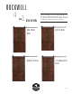
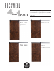
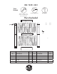
ROCKWELL 4in1 DOOR Choose between four door styles with this Door Kit. Our versatile Rockwell Door Kit is very easy to assemble. All materials and hardware needed to assemble any of the four styles are included. Tw o Panel D oor Hal f X Do o r D oubl e X Door Z Comb i n a t i o n Door 2.24.
ROCKWELL 4 1 dans PORTE Choisissez entre quatre styles de portes avec ce Kit de porte.
P L E A S E REA D th e s e i m port ant not if icat ions bef ore proceeding . If any of the slats have been damaged during shipping, call us at 800-891-8312 and we will expedite replacement slat(s) or parts as needed. Lay out your Door slats and parts according to the illustration shown at right to accurately identify which part needs to be replaced, if any. PLEASE NOTE: These instructions are specific to a particular door size and type.
V EUI LLEZ LIRE ces im portant es mi s es en garde avant de c ont i n u e r. Si l'une des lattes a été endommagée pendant le transport, appelez-nous au 800-891-8312 et nous enverrons les lattes ou pièces de remplacement selon les besoins. Disposez vos lattes de porte et composants selon l’illustration montrée à droite pour accurately identify which part needs to be replaced, if any. Veuillez noter: ces instructions sont spécifiques à un type et à une taille de porte particuliers.
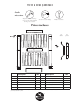
Two Panel Door Tools Needed Drill with Phillips bit Ratchet with 7/16” deep socket or a standard 7/16” socket with extension Rubber Mallet Parts Included A4 D1 x8 front view side view A1 L C1 C2 C2 C2 C2 C2 C3 C2 A1 R E x 36 A3 B1 B2 B2 B2 B2 B2 B2 F B3 A2 Description Qty Description Qty A1 L Side Stile Left 1 C1 C3 Top End Slats 1 each A1 R Side Stile Right 1 C2 Top Center Slats 6 each* A2 Bottom Rail 1 B1 B3 Bottom End Slats 1 each A3 Middle Rail 1 B2
Porte à d e u x p a n n e a u x Outils nécessaires Cliquet avec douille de 7/16 po ou une prise de courant standard de 7/16 po avec extension Perceuse avec mèche Phillips Maillet en caouchouc Pièces incluses A4 D1 x8 Vue frontale Vue latérale A1R A1L C1 C2 C2 C2 C2 C2 C2 C3 E x 36 A3 B1 B2 B2 B2 B2 B2 B2 B3 F A2 Description Qté Description extrémité supérieure des lattes Qté A1 G Latte avec montant à gauche 1 C1 C3 A1 R Latte avec montant à droite 1 C2 A2 Rail inférie
NOTE: Your door has a mortise (a 1/2” groove that runs along the bottom of your door) that will house the door guide. When assembling the door make sure that all pieces with a mortise (pieces A1 and A2) are oriented with the mortise facing down toward the bottom of the door (the side that will be closest to the floor when the door is hung). Door bottom with mortise Two Panel Door Assembling Your Door - Lay out your door as shown below. 1. Slide all B slats to the right into A1 R.
NOTE : Votre porte comporte une mortaise (unr rainure de 1/2 po qui longe le bas de votre porte) et qui abritera le guide de la porte. Lors de l’assemblage de la porte s’assurer que toutes les pièces avec une mortaise (pièces A1 et A2) sont orientées avec la mortaise vers le bas, vers le bas de la porte (le côté qui sera plus proche du sol quand la porte sera accrochée).
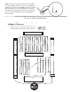
Two Panel Door 2. Slide Center Rail A3 down on top of the B Slats and into Side Stile A1 R. Gently tap with a rubber mallet. 7 /16” 3. Slide all C Slats down and to the right into Center Rail A3 and Side Stile A1 R. Then slide top rail A4 down over the tops of the C Slats. Gently tap with a rubber mallet. 7 A4 A1 L C1 C2 C2 C2 /16” A4 C2 C2 C2 C3 A1 R A1 L C1 C2 C2 C2 C2 C2 C2 C3 A1 R A3 A3 B1 B2 B2 B2 B2 B2 B2 B3 B1 B2 B2 B2 B2 B 2 B2 B3 A2 A2 4.
porte à d e u x p a n n e a u x 2. Faites glisser le rail central A3 au dessus des lattes B et dans le montant latéral A1. Tapotez doucement avec un maillet en caoutchouc. 3. Glissez toutes les lattes C vers la droite dans le rail central A3 et le montant latéral A1 R. Puis faites glisser la glisser traverse supérieure A4 par dessus les lattes C. Tapotez doucement avec un maillet en caoutchouc.
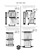
Half X Door Complete Steps 1 through 5 from Pages 4 and 5. 6. When the Door is assembled, place A5, A6 and A7 (Diagonal Rails) onto the door’s bottom panel so the predrilled holes are facing up and so they form an X that runs from corner to corner. Attach using the 3/4” Grabber Screws and a drill with a Phillips bit. Attach the Door Pull and your Door is ready to hang.
D emi p o r te X Suivez les étapes 1 à 5 aux pages 4 et 5. 6. Lorsque la porte est assemblée, placer A5, A6 et A7 (les rails diagonaux) sur le panneau inférieur de la porte si les trous sont vers le haut de façon à former un X d'un angle à l'autre. Fixez à l’aide de la vis Grabber 3/4" et d'une perceuse avec une mèche Phillips. Fixez la porte, tirez et votre porte est prête à être suspendue.
Z Combination Door Complete Steps 1 through 5 from Pages 4 and 5. 6. When the Door is assembled gently tap all parts into place with a rubber mallet. Place both A5 Diagonal Rails onto the door so the predrilled holes are facing up and so they run the same way, from corner to corner. Attach using the 3/4” Grabber Screws and a drill with a Phillips bit. A5 E1 x 36 A6 7. Attach the Door Pull and your Door is ready to hang.
Port e co mb i n a i so n Z Suivez les étapes 1 à 5 aux pages 4 et 5. 6. Une fois la porte assemblée, tapotez doucement avec un maillet en caoutchouc pour mettre les pièces en place. Placez les deux rails en diagonale A5 sur la porte afin que les trous soient vers le haut, et soient alignés de la même manière, d'un coin à l'autre. Fixez à l’aide de la vis Grabber 3/4" et d'une perceuse avec une mèche Phillips. A5 E1 x 36 A6 7. Fixez la porte, tirez et votre porte est prête à être suspendue.
Double X Door Complete Steps 1 through 5 from Pages 4 and 5. A5 A6 6. When the Door is assembled, gently tap all parts into place. Place A5, A6 and A7 (Top Diagonal Rails) onto the door so the predrilled holes are facing up and so they form an X that runs from corner to corner. Attach using the 3/4” Grabber Screws and a drill with a Phillips bit. Repeat for B5, B6, and B7 (Lower Diagonal Rails). A7 Attach the Door Pull and your Door is ready to hang.
Porte d o u b l e X Suivez les étapes 1 à 5 aux pages 4 et 5. A5 A6 6. Une fois la porte assemblée, tapotez doucement pour mettre les pièces en place. Placer A5, A6 et A7 (les rails diagonaux supérieurs ) sur la porte si les trous sont vers le haut de façon à former un X d'un angle à l'autre. Fixez à l’aide de la vis Grabber 3/4" et d'une perceuse avec une mèche Phillips. Répéter pour B5, B6 et B7 (rails latéraux inférieurs). Fixez la porte, tirez et votre porte est prête à suspendre.
Installing the Falcon Door Pull The location where you attach your Door Pull is up to you. We suggest you don’t attach your Door Pull too close to the edge of your Door or a seam, as this could weaken the integrity of your Door. Typically we recommend that the center of your Door Pull be lined up 3’ from the bottom of the door. 3 ft.
I n st allat ion de la p o i g n é e d e p o r te Fa l co n Il vous appartient de décider où affixer les poignées de votre porte. Nous suggérons que vous ne fixiez pas les poignées de votre porte trop près du bord de des jointures, car cela pourrait fragiliser l’intégrité de votre porte. En général, il est recommandé de laisser un espace d'environ 3 po entre le sol et le bas de votre porte. 3 pi.
Installing the I ndustrial Hardware System 1. Measuring and Marking Your Hanger Holes 2. Drilling Pilot Holes Door Top • Lay your Door facing UP on saw horses. • Pencil a line 2” parallel from the Door edge (this " marks the proper location for the Hanger edge). • Using your Hanger as a guide, line up your Hanger with the line you just made. • Holding your Hanger in place, measure a 2-3/8” gap between the top of the Door and the bottom of the Wheel (see below).
I n s t a l lat ion du s y s t ème d e q u i n ca i l l e ri e i n d u stri e l l e 1. Mesurer et marquer vos trous de suspension 2. Perçage des trous de guidage Dessus de la porte • Mettre la porte à plat sur des trétaux, face intérieur vers le haut. • Marquer une ligne au crayon 2 po à l'intérieur de l'angle " de la porte (cela marque l'emplacement du rebord de la suspente) * • En utilisant votre suspente comme un guide, alignez votre suspente avec la ligne que vous venez de tracer.
Installing the Industrial Hardware System 1. Installing Your Hanger Assembly To Your Door 2. Tightening Your Hanger Assembly • Thread the Hex Bolts with the Washers through the back of the Door. • Thread the Hanger assembly through the Hex Bolts on the front of the Door. • Holding Hex Bolts in place using a ratchet with a 5/8” socket, lightly tighten your Acorn Nuts by hand.
I n s t a llat ion du s y s t ème d e q u i n ca i l l e ri e i n d u stri el l e 1. Assemblage de la suspente à votre porte 2. Reserrage de votre assemblage de suspente • Faites passer les boulons et les rondelles par l'arrière de la porte. • Faites passer l'assemblage dans les boulons hexagonaux à l'avant de la porte. • Maintenant les boulons en place à l'aide d'une clé à cliquet et une douille 5/8 po, resserrer les Écrous borgnes à la main.
Installing a Header Measuring for your Track holes On your Header, measure in 3” from the end and 4“ from the top and 2” from the bottom of the header. 3” 4” 4” 2” 2” 3” Attaching Header Place your Header onto your wall with the bottom 2” of the Header below your marked track line. Have someone hold the Header in place while you continue your pencil line for the holes in your Track from your wall onto the Header. Ensure your line is plumb using a level.
Ins tallati o n d 'u n e n -tê te Mesures pour vos trous de piste Sur votre tête, mesurer en 3 po depuis le bas et 4 po depuis haut et 2 po depuis le fond de l’en-tête. 3 po 4 po 4 po 2 po 2 po 3 po Fixation de l'en-tête Placez votre tête sur votre mur avec les 2 po du bas de l’en-tête en dessous de la ligne de piste précédemment tracée. Demandez à quelqu'un de tenir l’en-tête en place pendant que vous continuez votre tracé au crayon des trous le long de votre piste depuis votre mur sur l’entête.
If you are installing a Flat Track System, proceed. If you are installing a Tube, Box, Bypass, J or Heavy-Duty Bypass Track System, call our helpful Customer Service Representatives for instructions on how to install these track systems. The number of holes in your Track depends on the length of track ordered. Measuring for Track Position 1-5/8” Door Height } 1-5/8” + Door Height + 1/2” = # of inches up from your =finished floor where you will pencil a horizontal line for your Track.
Si vous installez un système de piste plate, allez de l'avant. Si vous installez un Tube, boîte, Bypass, J ou système de piste par Bypass, appelez nos sympatiques télé-conseillers pour obtenir des instructions sur la façon d’installer ces systèmes de rail. Mesure du positionnement de la piste 1-5/8 po Hauteur de la porte } Le nombre de trous dans votre piste dépend de la largeur de la porte et la longueur de piste choisie.
Installing Track Installing the a Header 2. Hanging Your Track • Loosely attach one end of the Track using a Spacer and a Hard Stop or a Lag Soft Stop (see below). • Swing the Track up and loosely attach the other end, using a Spacer and a Hard Stop or a Lag Soft Stop (see below). 3. Hole Installation • The center holes can now be loosely attached (see below). 9/16” • The end holes will be installed with a Hard Stop. • In this order: Adjustable Spacer, Flat Track, Hard Stop, 1” Washer, and Lag Screw.
Ins tallati o n d'un d e l a en-tête p i ste Installation 2. Suspension de la piste • Attachez une extrémité de la piste à l'aide d'une cale d’espacement et un arrêt dur ou d'un stoppeur mou (voir ci-dessous). • Faites basculer la piste vers le haut et attachez l'autre extrémité à l'aide d'une cale d’espacement et un arrêt dur ou d'un stoppeur mou (voir ci-dessous). • Les trous centraux peuvent maintenants être fixés (voir ci-dessous) 3.
Installing the Door Guide and Anti-Jump Bracket 1. Installing Your Door • Lift your Door up to your Track at a slight angle. • Carefully rest both Wheel grooves onto the top of the track. • Guide the Door to the resting position. 4. Aligning Anti-jump Bracket • Place your Anti-jump Bracket against the outside edge of your Door. • Slide the Bracket up until there is a 1/16” to 1/8” space between the top of the Anti-jump Bracket and the bottom of the Track. 2. Door Guide Part 1 3.
I n s t a l l at ion du guide le l a p o r te e t d u su p p o r t a n ti -sa u t 1. Installation de votre porte 2. Guide de porte partie 1 • Relever votre porte jusqu'à votre piste avec léger angle. • Mettez les deux roues en place sur la piste au dessus de la piste. • Guidez la porte en position de repos. 4. Alignement du support anti-saut • Placez votre support anti-saut contre l'angle extérieur de votre porte.
WE LOVE WHAT YOU’RE DOING WITH THE PLACE Congratulations on your decision to bring home an American-made product of the highest quality. We hope your piece brings art and function into your life.
NOUS VOUS FÉLICITONS POUR VOS RÉNOVATIONS Félicitations pour votre décision de ramener chez vous un produit de fabrication américaine de grande qualité. Nous espérons que cet ajout apporte fonctionnalité et élégance à votre vie.