INSTALLATION INSTRUCTIONS AIR-COOLED CONDENSING UNITS refrigerant (-)ANL-*AZ MODEL SERIES – 13 SEER (-)APL-JAZ MODEL SERIES – 14 SEER (-)APM-JAZ MODEL SERIES – 14.5 SEER ! RECOGNIZE THIS SYMBOL AS AN INDICATION OF IMPORTANT SAFETY INFORMATION! ! WARNING THESE INSTRUCTIONS ARE INTENDED AS AN AID TO QUALIFIED, LICENSED SERVICE PERSONNEL FOR PROPER INSTALLATION, ADJUSTMENT AND OPERATION OF THIS UNIT. READ THESE INSTRUCTIONS THOROUGHLY BEFORE ATTEMPTING INSTALLATION OR OPERATION.
TABLE OF CONTENTS Checking Product Received . . . . . . . . . . . . . . . . . . . . . . . . . . . . . . . . . . . . .2 Dimensions . . . . . . . . . . . . . . . . . . . . . . . . . . . . . . . . . . . . . . . . . . . . . . . . . .3 Electrical & Physical Data . . . . . . . . . . . . . . . . . . . . . . . . . . . . . . . . . . . . . . .4 General . . . . . . . . . . . . . . . . . . . . . . . . . . . . . . . . . . . . . . . . . . . . . . . . . . . . .5 Application . . . . . . . . . . . . . . . . . . . . . . . .
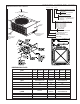
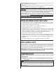
UNIT MODEL NUMBER EXPLANATION FIGURE 1 DIMENSIONS AND INSTALLATION CLEARANCES (-) A N L – 024 J A Z COOLING CONNECTION FITTING Z - SCROLL COMPRESSOR VARIATIONS A - Series = FULL FEATURED AIR DISCHARGE ALLOW 60” [1524 mm] CLEARANCE ELECTRICAL DESIGNATION J = 208/230V-1-60 C = 208/230V-3-60 [Available only on (-)ANL- Models] D = 460V-3-60 Y = 575V-3-60 } BTU/HR x 1000 (COOLING CAPACITY) 018 = 18,000 BTU/HR 024 = 24,000 BTU/HR 030/031 = 30,000 BTU/HR 036/037 = 36,000 BTU/HR 042/043 = 42,000 BTU/HR 048/04
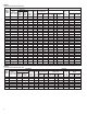
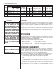
TABLE 1 (-)ANL ELECTRICAL AND PHYSICAL DATA Model Number (-)ANL- 018JAZ 024JAZ 030JAZ 031JAZ 036CAZ 036DAZ 036JAZ 037CAZ 037DAZ 037JAZ 042CAZ 042DAZ 042JAZ 043CAZ 043DAZ 043JAZ 048CAZ 048DAZ 048JAZ 048YAZ 049CAZ 049DAZ 049JAZ 049YAZ 060CAZ 060DAZ 060JAZ 060YAZ ELECTRICAL PHYSICAL Compressor Fuse or HACR Fan Motor Minimum Refrig. Outdoor Coil Phase Circuit Breaker Rated Locked Full Load Circuit Per Frequency (Hz) Load Rotor Amperes Ampacity Circuit Minimum Maximum Face Area No.
TABLE 3 (-)APM ELECTRICAL AND PHYSICAL DATA ELECTRICAL PHYSICAL Compressor Fuse or HACR Model Refrig. Fan Motor Minimum Outdoor Coil Phase Circuit Breaker Number Per Rated Load Locked Rotor Full Load Circuit Frequency (Hz) (-)APMCircuit Amperes Ampacity Minimum Maximum Face Area No. Amperes CFM Voltage (Volts) Amperes Oz. [g] (FLA) Amperes Amperes Amperes Sq. Ft.
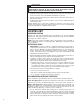
! WARNING DISCONNECT ALL POWER TO UNIT BEFORE STARTING MAINTENANCE. FAILURE TO DO SO CAN CAUSE ELECTRICAL SHOCK RESULTING IN SEVERE PERSONAL INJURY OR DEATH. • Frequent washing of the cabinet, fan blade and coil with fresh water will remove most of the salt or other contaminants that build up on the unit. • Regular cleaning and waxing of the cabinet with an automobile polish will provide some protection. • A liquid cleaner may be used several times a year to remove matter that will not wash off with water.
CUSTOMER SATISFACTION ISSUES • • The condenser should be located away from the living, sleeping and recational spaces of the owner and those spaces on adjoining property. To prevent noise transmissionm, the mounting pad for the outdoor unit should not be connected to the structure, and should be located sufficient distance above grade to prevent ground water from enteriing the unit. PROPER INSTALLATION Proper sizing and installation of equipment is critical to achieve optimal performance.
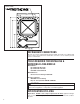
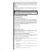
FIGURE 2 SCREW LOCATIONS REFRIGERANT CONNECTIONS All units are factory charged with Refrigerant 410A. All models are supplied with service valves. Keep tube ends sealed until connection is to be made to prevent system contamination. TOOLS REQUIRED FOR INSTALLING & SERVICING R-410A MODELS Manifold Sets: -Up to 800 PSIG High side -Up to 250 PSIG Low Side -550 PSIG Low Side Retard Manifold Hoses: -Service Pressure Rating of 800 PSIG Recovery Cylinders: -400 PSIG Pressure Rating -Dept.
Physical Properties: R-410A has an atmospheric boiling point of -62.9°F and its saturation pressure at 77°F is 224.5 psig. Composition: R-410A is an azeotropic mixture of 50% by weight difluoromethane (HFC-32) and 50% by weight pentafluoroethane (HFC-125). Pressure: The pressure of R-410A is approximately 60% (1.6 times) greater than R-22. Recovery and recycle equipment, pumps, hoses and the like need to have design pressure ratings appropriate for R-410A.
NOTE: & (-)APM units must with a TEV Evaporator. NOTE: All All (-)ANL, (-)ANL (-)APL units must be installed withbea installed TEV Evaporator. The thermostatic expansion valve is specifically designed to operate with R-410A. DO NOT use an R-22 TEV or evaporator. The existing evaporator must be replaced with the factory specified TEV evaporator specifically designed for R-410A. LOCATION Do not install the indoor evaporator coil in the return duct system of a gas or oil furnace.
5. Capillary Tube Coil: DO NOT exceed the Table values for vertical separation for capillary tube coils. 6. Always use the smallest liquid line size permitted to minimize the system charge. 7. Table Table 64 may may be be used for sizing horizontal runs. OUTDOOR UNIT BELOW INDOOR COIL Keep the vertical separation to a minimum. Use the following guidelines when installing the unit: 1. DO NOT exceed the vertical vertical separations separations as as indicated indicated on on Table Table 5. 6. 2.
TABLE 5 SUCTION LINE LENGTH/SIZE AND CAPACITY MULTIPLIER Unit Size 11⁄2 Ton 2 Ton 21⁄2 Ton 3 Ton 31⁄2 Ton 4 Ton 5 Ton Suction Line Connection Size 3/4" I.D. 3/4" I.D. 3/4" I.D. 7/8" I.D. 7/8" I.D. 7/8" I.D. 7/8" I.D. 5/8 5/8 5/8 3/4 3/4 7/8 7/8 Suction Line Run - Feet 3/4* 3/4* 3/4* 7/8* 7/8* 1 1/8* 1 1/8* 25’ 50’ 100’ 150’ — — 7/8 — — — — Optional 1.00 1.00 1.00 1.00 1.00 1.00 1.00 Standard 1.00 1.00 1.00 1.00 1.00 1.00 1.00 Optional — — 1.
TABLE 6 LIQUID LINE SIZE — OUTDOOR UNIT ABOVE INDOOR COIL System Capacity Line Size Connection Line Size Size (Inch O.D.) (Inch I.D.
LEAK TESTING • Pressurize line set and coil through service fittings with dry nitrogen to 150 psig maximum. Leak test all joints using liquid detergent. If a leak is found, recover pressure and repair. ! WARNING DO NOT USE OXYGEN TO PURGE LINES OR PRESSURIZE SYSTEM FOR LEAK TEST. OXYGEN REACTS VIOLENTLY WITH OIL, WHICH CAN CAUSE AN EXPLOSION RESULTING IN SEVERE PERSONAL INJURY OR DEATH. EVACUATION PROCEDURE Evacuation is the most important part of the entire service procedure.
The installers should balance the air distribution system to ensure proper quiet airlow to all rooms in the home. This ensures a comfortable living space. These simple mathematical formulas can be used to determine the CFM in a residential or light commercial system. Electric resistance heaters can use CFM = volts x amps x 3.414 1.08 x temp rise Gas furnaces can use CFM = BTUH ∆T x 1.08 An air velocity meter or airflow hood can give a more accurate reading of the system CFM’s.
3. 4. 5. Read and record the indoor ambient wet bulb temperature entering the indoor coil. Use the appropriate charging chart to compare the actual liquid pressure to the correct pressure as listed on the chart. R-410A charging charts are listed on the unit. ! CAUTION R-410A PRESSURE ARE APPROXIMATELY 60% HIGHER THAN R-22 PRESSURES. USE APPROPRIATE CARE WHEN USING THIS REFRIGERANT. FAILURE TO EXERCISE CARE MAY RESULT IN EQUIPMENT DAMAGE, OR PERSONAL INJURY.
DO NOT connect aluminum field wire to the contactor terminals. GROUNDING A grounding lug is provided near the contactor for a ground wire. ! WARNING THE UNIT MUST BE PERMANENTLY GROUNDED. FAILURE TO DO SO CAN CAUSE ELECTRICAL SHOCK RESULTING IN SEVERE PERSONAL INJURY OR DEATH. FIGURE 3 CONTROL WIRING FOR GAS OR ELECTRIC HEAT FOR TYPICAL GAS OR OIL HEAT FOR TYPICAL ELECTRIC HEAT TABLE 8 Thermostat Load - Amps FIELD WIRE SIZE FOR 24 VOLT THERMOSTAT CIRCUITS SOLID COPPER WIRE - AWG. 3.0 2.5 2.
HIGH AND LOW PRESSURE CONTROLS (HPC OR LPC) These controls keep the compressor from operating in pressure ranges which can cause damage to the compressor. Both controls are in the low voltage control cir-cuit. High pressure control (HPC) is a manual reset which opens near 610 PSIG. Do not reset arbitrarily without first determining what caused it to trip. The low pressure control (LPC) is an automatic reset which opens near 50 PSIG and closes near 95 PSIG.
HARD START COMPONENTS Start components are not usually required with the scroll compressors used in (-)ANL/(-)APL/(-)APM condensing units, but are available for special cases and where start components are desirable to reduce light dimming. TIME DELAY CONTROL (TDC) The time delay (TDC) is in the low voltage control circuit.
TROUBLE SHOOTING In diagnosing common faults in the air conditioning system, it is useful to present the logical pattern of thought that is used by experienced technicians. The charts which follow are not intended to be an answer to all problems, but only to guide your thinking as you attempt to decide on your course of action. Through a series of yes and no answers, you will follow the logical path to a likely conclusion. Use these charts as you would a road map, if you are a beginning technician.
MECHANICAL CHECKS FLOW CHART Unit Running? YES NO Pressure problems? Go to Electrical Checks Flow Chart High Head Pressure Low Head Pressure Low Suction Pressure Dirty Condenser Coil Low on Charge Dirty Filters Inoperative Outdoor Fan Open IPR Valve Dirty Evaporator Overcharge Low Ambient Temperature Inadequate Airflow Recirculation of Condenser Air Inoperative Compressor Valves Broken Indoor Blower Belt Non-condensibles Restricted Filter-drier Inoperative Indoor Blower Higher than Am
SUPERHEAT CALCULATION TABLE TABLE12 9 TEMPERATURE TEMPERATURE PRESSURE PRESSURE CHART 22 TEMP (Deg. F) R-410A PSIG -150 -140 -130 -120 -110 -100 -90 -80 -70 -60 -50 -40 -35 -30 -25 -20 -15 -10 -5 0 5 10 15 20 25 30 35 40 45 50 55 60 65 70 75 80 85 90 95 100 105 110 115 120 125 130 135 140 145 150 — — — — — — — — — 0.4 5.1 10.9 14.2 17.9 22.0 26.4 31.3 36.5 42.2 48.4 55.1 62.4 70.2 78.5 87.5 97.2 107.5 118.5 130.2 142.7 156.0 170.1 185.1 201.0 217.8 235.6 254.5 274.3 295.3 317.4 340.6 365.1 390.9 418.
TROUBLE SHOOTING CHART ! WARNING DISCONNECT ALL POWER TO UNIT BEFORE SERVICING. CONTACTOR MAY BREAK ONLY ONE SIDE. FAILURE TO SHUT OFF POWER CAN CAUSE ELECTRICAL SHOCK RESULTING IN PERSONAL INJURY OR DEATH.
FIGURE 4 SINGLE-PHASE WIRING DIAGRAM 24
FIGURE 5 THREE-PHASE WIRING DIAGRAM (C, D & Y VOLTAGES) 25
FIGURE 6 26
CM 0908