Commercial High Efficiency Walter Heater USE & CARE MANUAL WITH INSTALLATION INSTRUCTIONS FOR THE CONTRACTOR For use with the following models: &: HUGHES, HUGHES I E GHE1008S, GHE1008U CATEGORY IV Models Fan Assisted Combustion Recognize this symbol 8 an indication of important safety information] D not destroy this manual. Pleads read carefully and keep in a safe place for future reference.
TABLE OF CONTENTS Safety Information Housefly Precautions . 34 introduction Oval Installation Regulations .. 5 Water Healer e 8 Installation instructions Inspect Shipment . 8 Water Supply Conclusions ...conciseness B Gas Supply. . . B Vent Installation Information for Alps and Fittings. . . .8 General Venting Information .. .8 Joining Pipe and Fittings %10 Vet Length Information. . Vent Terminal Precautions 1316 Horizontal Vent Installation. 17-19 Vertical Vent Installation .. Concentric Vent installation .
A General Safety Precautions Be sure to read and understand the entire Use & Care Manual before tempting to install or operate this wale Hester. Especially the following General Safety Precautions. Failure to follow these warnings could result in a fire or explosion, causing property damage, badly in fury, or death. Should you have any problems understanding the instructions in this manual, STOP, and get halo from a qualified Installer, service technician, or gas supplier. £\ WARNING Gasoline, as well a8 ot
LOCAL INSTALLATION REGULATIONS This wale heater must be installed in accordance with these instructions, local codes, and utility company requirements, In the absence of local codes, the latest entitle of the Natl! Fuel Gas Code, ANSI 22231 In the United States, or CANCAN B149.1 Installation Codes in Canada should be consulted. LOCATION A.
Installation setting of the relief valve, causing it to operate during sate heating cycle. Thermal expansion, and the resulting rapid, repeated expansion and contraction of components in the water heater and piping system can cause premature allure of the relief valve and possibly the heater selfish.
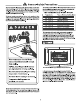
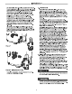
Installation the manual gas shut-off valve near the water heater. Use 2 soapy wale solution o test for gas leaks at all connections and filings. Bubbles Indicate 2 gas leak that must be corrected. The wale heater factory connections to the gas valve should also be leak tested after placing the water heater in operation.
AL WARNING Failure to properly vent the wale heater i e outdoors as outlined above and In the following section can result In unsafe personage the wale heater causing bodily injury, explosion, freer 4\ WARNING NOTICE: DO NOT use in conjunction with a CLOG To avoid the risk of firs, explosion o inspiration from carbon monoxide, NEVER operate this water heater unless i ls propped vented and has an adequate alr supply for proper perversion.
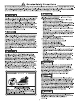
PVC (Schedule 40 DWV, MAST F-438) ABS (Schedule 40 DWV, MAST permitted in Canada} HOGTIE: Use of PYC cellular core [ASTM-FB31], ABS Schedule 40, DWV cellular core [ASTHMA -F828}, or Ruads!® polyphenyisulfons) in non-metallic venting systems is prohibited. The unit may be versed horizontally through a wall ar vertically through the roof. Pipe runs must be adequately supported along both vertical and horizontal runs. Maximum unsupervised span Is recommended to be no more than 4 fest.
# For applications below 32°F use only low temperateness type solvent cement. ® Appropriate sloven! and cleaner must be used for the type of vent pipe used (PVC, PVC, PR, or ABS). DANGER OF FIRE OR BODILY INJURY Solvent cements and primers are highly flammable. Provide adequate ventilation and do not assemble near a hast source or open flame. DO NOT smoke. Avoid skin or eye contact. Observe all cautions and warnings on material containers.
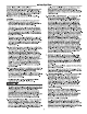
installation MINIMUM AND MAXIMUM VENT LENGTHS important information for all installations: 1} The minimum required venting is what is required io safely extend the inlet and outlast vent pipes outside of the building. 2 Each 90° slow {standard or long sweep elbow) reduces the equivalent vent length by 5 feet ) Each 45° skibob reduces the equivalent vent length by 2 1/2 fest 4} DO NOT mix pipe sizes for venting these models, use only one size of pipe for all venting.
Installation Max Vent Length (Ea.FL) Power Direct Sent Rigid Pipe Diameter Inlet Models Altitude Range idiot | Outlet | inlet | Outset | inlet | Outlet | Inset | Outlet ©0-2000 120 | 188 | s e-609m) | (B1m) (107m) (183m) (229m) (366m) (411 m) HEGOSU2001-6899 120 | 185 GHEBOSUIO0M) | (yo-zraarm) (zzm)| cosmos | @esm @am| WA | MA GHOSTLY-2001) 0-8000 120 | 136 | 120 | 138 2838 (107 m} (183w} | (229 | (36.8m) | (411 (41,1 ) 0-2000 120 | 185 | | e-609m | @Im) |po.7m GHE100SU-160 2001-8999 120 | 135 SUE | w10.
e Figueroa § ‘Chest stall Hashish on 11| o Brickwork Masonry Wald " Elbow can bo & redden Cont Ripe of 1 Ines from the wal. Fed | st Vet Terminator Coupling with U2* Mesh Pro- twentieth Serena Inside T the Water Hester Quasimodo of the Building Wil Figure & Typical Horizontal Vent Installation Additional Considerations (3se Figures 104 11) 1. DO NOT install vent terminals under any patio or deck. 2.
Installation » [ HOT terminate near offsite vents or craw! space or other area where condensate or caper could orate a nuisance hazard or cause property damage. * (30 HOT locates the exhaust vent terminal where condensation or vapor could cause damage or could be detrimental io the operation of regulators, relief valves, or other equipment. » DO NOT locate the exhaust vent terminal over public area or walkways where condensate or vapor can cause nuisance or hazard.
installation Figure 10Typlecal Horizontal Power Vent System EVERY 3 MaX. 2,3,4,0R6 INCH PIPE AND When 8 inch pipe is used, start pipe SUPPORT BRACKET FITTINGS supports as close as possible to unit 45° TERMINAL 1IN MALL WATER HESTER WALL DRAIN BAN FLOOR * A B inch pipe can be used on 300,000 Bitch models and above.
Installation Figure typicality Horizontal Direct Vent System EVERY 8 MAK SUPPORT BRACKET Wuhan & inch pips I suds, 2,3, 4, DR & INCH PIPE Tiers pips Nonsupport as clods. AND FITTINGS &8 possible to unit. TERMINAL e (W, MR WATER HEATER \— FLOOR \WALL * A 6 inch pipe can be used on 300,000 Btu/h models and above. Through The Wall Venting With Low Ground Clearance: Wuhan veining cannot exit through the wall at a height greater than or squeal fo 12" [30.
Installation Horizontal Venting Figure 12a: Multiple Unit Venting Figure 12c: Optional Configuration Example of 2 Units’ Vents. 247 1o 367 24" o 387 2497 1o 36 247 10 38" 24" Min. Haar:er#] 10 Min. Faamr#z intake Exhaust Figure 12b: Multiple Unit Venting Figure 11d: Optional Configuration NOTICE: 11¢ can also be configured for 4 units. Example of 4 Units' Vent. Hwtar#]1 24" Min. )Fflfllxr#i{ 12 M. 24°MIn. 107 Min. taints Exhaust intake Exhaust 24" w038 . 24”0 36 Heater 43 24" Min. )Femur i 12° Min. 24" Min.
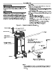
Installation Figure 14. Typical Carnival Power Sent System Installation Straight Exhaust Terminal Support Bracket . \ Recommended support bracket be placed on horizontal run S TN Alternate vertical venting with exhaust vent muted down Exhaust Terminal\ preferred for cold climates. Support Bracket Recommended support bracket be placed an horizontal run N Water Heater—|_ | Mir. above roof. Min. of 12" (30.5 cm} by participated snow level. Max. 24" (61 om) above bt without additional support.
Installation AL WARNING These instructions sre intended as an aid o qualified service personnel for proper Installation, adjustment, and operation of this kit Read these Instructions thoroughly before attempting Installation, adjustment, or aeration. Allure 1o follow theses instructions can result in improper installation, adjustment, service, or maintenance possibly resulting in fire, clericalism shook, property damage, personal Injury, or death. £\ WARNING This kit is 1o be used only for vent & combustion
Installation STEP 3: Figure 19 Multiple Sidewall or Vertical Secure the combustion ale-Inlet pipe using a flied Concentric Vents supplied perforated strap or a suitable type material {sas Figure Min. 35" (81 om} Min, STEP 4: Assemble the vent pipe assembly by cleaning and cementing the ran cap to the smaller diameter exhaust pipe. Assemble the 30° slow by cleaning and cementing i to the rain cap.
Installation PV pipe shipped with the unit PVC PP | | Pp Pipe adapter Straight piece of PP pipe contact PVC adapter vent terminal installed onto a PP 1o PVC adapter. Note: The hole through the wall should be sled for the PP pipe, which has a smaller OD than PVC pipe. The first step to install the PP pipe is 1o find a PVC to PP adapter and lubricate the gasket that will slide into the PVC fitting. Tha lubricant for the Endothermic parts is called Introversion.
Installation The PVC to PP adapter should then be installed into the PVC couplings on the infer air and exhaust vent installed on the uni. The sealing gasket will require some type of lubricant to make i easier to install the adapter. Both Endothermic and M&G Durante recommend a connector ring 1o be installed between the PVT part and the PP part. Tha connector ring for the Endothermic pipe {dither IACCOCA, NICOSIA, or JACOB) is shown blow.
Installation To be able tv use a PV termination, a short spice of PP pipe will need shown below, to transition from the bell end of the pipe 1o the PP to PVC adaption. Cut a piece of PP pipe that s long enough to go through the wall and have about 2" protruding on each side of the wall. The PP 1o PVC adapter can either be installed on the pipe or lino the vent terminal for the next step. The final step is to make sure the vent terminal is attached and secured to the adapter.
Installation Check List A. Water Heater Location D. Relief Valve 0 Close to ares of vent. L1 Discharge line run to open drain. U Indoors and protected from freezing temperatures. Discharge line protects from freezing. [l Proper clearance from combustible surfaces observed and wale heater is not installed ona E. Venting carpal floor. L] All pipe connections are secure (at blower, vent terminals and for each pipe joint connection), and [ Air supply free of corrosive elements and flammable Vapor S.
Operation Ha fore operating this water Hester, be sirs o read snd follow The instructions on e label pictured below and sl other labels and warnings on the warts heater and printed in this manual. Allures to do so can result in unsafe operation of the wale heater resulting in properly damages, Bodily in fury, or death.
Operation A DO wm off manual gas shut-off valve if wale heater has been subjected to over heating, fire, flood, physical damage or f gas supply fails to shut off. B. DO NOT tum on wale heater unless it s filed with water. G DO NOT tum on wale heater if cold wale supply shut-off valve is closed. 0. DO NOT stirs or uss gasoline or other flammable vapors and liquids, such as adhesives or paint inner, In vicinity of his or any other appliance.
BASIC SETTINGS: The basic settings in you water hater can allow you to sangs the temperature unit, screen adjustment sunblock, enabling/disabling the alarm beep, and your Evolve network instance. Simply select the setting by tapping ¥, and press the Up/Down arrows o make adjustments. WiFi setup can be accessed from this screen as well.
ALARMS: The current alarms function allows you to ses any problems that have bean detected by your water heater. Also, by selecting on the current alarm you can pass “more info” 1o read mots on the current problem of your water heater. Alarm history flows you 1o ses any of the previous alarms that have gone off in the past and give you the ability to clear those previous alarms. current alarms e e By sleeting “more info” you san be given a more in-depth explanation of the current alarm.
Maintenance Properly maintained, this water heater will provide years of dependable, ruble free service. It Is strongly suggested that a regular routine maintenance program be established and followed by the owner It is further recommended that a periodic inspection of the relief valve and venting system should be mads by service technicians qualified In gas appliance repair, 1. ROUTINE PREVENTIVE MAINTENANCE A.
Before You Gall For Service... Troubleshooting Tips Save them and money Review the charts on the following pages first and you may not need to call for service. If one of the health indicators is blinking on the home screen or the service icon is blinking there is an issue with the operation of your water heater. Pressing the service Status: Standby icon will allow you to look at Current Alarms {and Alerts), Alarm History, and Unit Health . screens for Issues that dean attention.
Before You Call For Service... Troubleshooting Tips Save time and money Review the charts on the Hollowing pages first and you may not ends to call for service. Problem Possible Cause ‘What To Do Unable to light the main burner Gas control problem Contact a qualified service technician. Unit or electrical supply line nof properly grounded Verify that the electrical supply line and unit have proper ground connection. Main burner does not stay lit Sumner flame not contacting sensor rod.
Before You Call For Service... failed ignitions. This will disable the heater. Alarm and Alert Description Current Alarm Screen Display (T} Codes ADD ignition lockout, A001 Ignition lockout due to & total of @ consecutive =»Clear error code by fuming the unit griffon. i probable persists, please contact technical support or service provider. APO Flame not stable lockout. Lost lame three times during une heat cycle. This will disable the heater. ADO Flame is not stable.
Before You Call For Service... Alarm (8% and Alert Description Current Alarm Screen Display {7’} Codes ADZE High Tank Temperature. Call Tech Service. ADZE Energy Cutout (ECO) switch is pane. This will emir code by pressing clear button. disable the heater. Refer to use and care manual for troubleshooting, or contact technical support. Flue {exhaust) gas temperature has exceeded AD High Flue Temp. Recycle unit ON/OFF, ~=Blower will continue to run until exhaust GAIT | 455°F This will disable the heater.
Before You Call For Service... Alarm and Alert Codes Description Current Alarm Screen Display Control does not detect blower RPM. This will ADZE No Blower RPM feedback. Call Tech Service ADS disable the heater. -»Please contact technical supper or service provider. ADZE Blower expected RPM vs actual RPM AD Blower RPM feedback (actual RPM) is 2300 mismatch RPM from desired RPM for > 1 minute. -Please contact technical support or service provider, Algal Flame present before ignite.
Before You Call For Service... Alarm ('A% and Alert Description Current Alarm Screen Display Codes Gas relay #2 contacts failed to properly close. . AORTA This can cause gas valve cycling and gas ogggsfzgm‘ i zm::e buildup in the bum chamber. This will disable cal support of service divider the heater, Ppo P : Gas relay #2 stuck closed. This could inadvertence Gas Relay 2 stuck closed. Call Tech Sve. ADOBE tenthly allow the gas valve to open.
Before You Call For Service... Alarm and Alert Codes Description Current Alarm Screen Display Check to ses if leak sensor is installed in the bottom Water Leak Sensor Not Installed -»Check water leak sensor connection. Refer T105 on connector P11 of the to use and care manual for troubleshooting, or o . contact technical support. Communication lost between the display board and the ignition control board.
Before You Call For Service... Alarm and Alert Description Current Alarm Screen Display (T} Codes TH7 Time to Drain and Inspect Tank Y Periodic maintenance, inspection, and upkeep -fore to the use and care manual for inn the unit st ructions, or contact technical support or service provider. T118 Time to Check Venting for Debris Periodic maintenance, inspection, and upkeep -»Refer to the use and care manual for henceforth unit. mason, or contact technical support or service provider.
Before You Call For Service... Alarm ('A) and Alert (T} Codes Description Current Alarm Screen Display Anode "open” circulate. This can be caused by T128 Middle Anode Open wiring connections for the middle Tizz damage, wiring disconnected, or anode anode. if error persists, please contact technical ge. support or service provider. T128 Middle Anode Mounting Error T120 Anode control common and the power connection wiring connections for the middies son for this anode cross connected. anode.
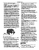
Replacement Parks Instructions For Placing a Parks Order All parts orders should include: Part description {as noted below) and number of ; parts desired. The model and serial number of the water heater from the rating plate. 4% CAUTION: For your safely DO NOT pattern repair of gas piping, Specify type of gas (natural or LP) as marked on a8 control boomer, vent connectors of other safety devices. Feeler ihe rating plate. repairs to qualified service personnel. Display Kit Side Pansy Covers \1 POF & Intake P
1. should you have any questions about your new water heater, or if it requires adjustment, repair, or routine maintenance, it is suggested that you first contact your installer, plumbing contractor or previously agreed upon service agency. In the event that the firm has moved, or is unavailable, refer fo the telephone directory commercial listings or local utility for qualified service assistance. .