Victrix Zeus 20/27 Instructions VICTRIX ZEUS 20/27 Instruction Booklet Eco-friendly wall-hung condensing boilers with stainless steel storage tank Read these instructions completely before using or installing the Victrix Zeus 20/27 gas boilers LEAVE THESE INSTRUCTIONS WITH THE USER For Technical assistance, spare parts or service call: RVR Limited, Kenmare, Co. Kerry Tel: 064 41344, Fax: 064 89520 Doc. Ref.
Victrix Zeus 20/27 Instructions Introduction The Victrix Zeus 20/27 boilers are condensing wall hung, room sealed combination boilers incorporating a 54 litre unvented hot water storage cylinder. This boiler has the highest efficiency possible for a gas boiler, ie 4 stars (****) in conformity with European Directive 92/42 EEC. The boiler, providing both central heating and domestic hot water supply, is designed for use with a fully pumped, sealed and pressurised heating system using Natural Gas or LPG.
Victrix Zeus 20/27 Instructions PERFORMANCE: Nominal Heat Input Min. Heat Input Nominal Heat Output (useful) Min. Heat Output GAS: Nozzle diameter Supply Pressure Kw Kw Kw Kw mm Mbar Victrix 20 Victrix 27 24.0 5.0 23.5 4.7 32.6 6.6 32 6.3 G20 G30 G31 G20 G30 G31 5.0 20 3.8 29 3.8 37 7.0 20 5.0 29 5.0 37 HEATING SYSTEM: Max Operating Pres. of Heating Unit bar 3 3 Max Operating Temp.
Victrix Zeus 20/27 Instructions Main Boiler Components Gas System Return System DHW Flow Outlet Cold DHW Inlet 1.Intake sockets (A= air) (F=fumes) 13. System filling cock 25.3-bar safety valve 2.Combustion chamber cover 14.Expansion vessel 26.8-bar safety valve 3.Ignition electrodes 15.Combustion chamber 27.Gaudium Magnum device 4.Detection electrode 16.SS storage tank 316L 28.Boiler emptying cock 5.Heating and limit NTC probe 17.Condensation module 29.Flue hood 6.Venturi duct 18.
Victrix Zeus 20/27 Instructions General Installation Information Gas Supply The meter and supply pipes must be sized to deliver the gas rate and pressure given on page 3. The boiler requires at least a 22 mm (3/4”) gas supply pipe. The complete installation, including the meter, must be tested for gas soundness and purged as described in IS 813:2002. Electrical Installation The boiler requires a 220/240 V ~ 50 Hz mains supply, fused at 3 A. The boiler must be earthed.
Victrix Zeus 20/27 Instructions Flue Systems When the boiler is installed on an external wall, the standard horizontal concentric 60/100 flue kit will normally be used to flue the boiler. This is shown in the diagram. It is often necessary to install a longer flue system to cater for site conditions. There are several different flue system sizes available for the Victrix Zeus 20/27 boiler.
Victrix Zeus 20/27 Instructions Separated Flue Systems Separated 80/80 flue kit This kit enables separation of the exhaust and air intake pipes as shown in the figure. Combustion products are expelled from pipe (A) (in plastic material resistant to acidic condensates). Air is taken in through pipe (B) (also in plastic material) for combustion. Intake pipe (B) can be installed either on the right or left hand side of the central exhaust pipe (B). Both pipes can be oriented in any direction.
Victrix Zeus 20/27 Instructions Flue calculations for more complex systems Each component of the air inlet/flue system has a resistance factor . These are given in the following tables. The resistance factor varies depending on whether the component in question conveys fresh inlet air or hot combustion gases. All boilers have a maximum resistance factor of 100. The sum of all components in the flue system must not exceed the maximum overall resistance factor of 100.
Victrix Zeus 20/27 Instructions Example: Flue system consists of 9m of 80mm air intake pipe with 3 x 90˚ bends and 6m of exhaust pipe with 2 x 90˚ bends. Component Resistances: Component Resistance Quantity Total 80mm Intake pipe 0.87 9 7.83 90˚ air intake bend 1.9 3 5.7 80mm Flue pipe 1.2 6 7.2 90˚ Flue bend 2.6 2 5.2 In this case the total resistance of the system is less than 100. The flue design is acceptable. Total Flue Resistance 25.
Victrix Zeus 20/27 Instructions Terminal Position Min. Distance A Directly below an opening, air brick, windows, etc.
Victrix Zeus 20/27 Instructions Boiler Location The boiler is not suitable for external installation. The boiler must be installed on a flat vertical wall which is capable of supporting the weight of the boiler. The boiler can be fitted to or adjacent to a wall comprising of a combustible material without the need for a special thermal insulation barrier.
Victrix Zeus 20/27 Instructions Central Heating System The boiler is designed for use in a sealed central heating system. The system should be designed to operate with flow temperatures of up to 80°C. When designing the system, the pump head, expansion vessel size, mean radiator temperature, etc. must be taken into account. The pressure losses in the system must be compatible with the boiler circulation pump.
Victrix Zeus 20/27 Instructions The most important components of the system are shown in the diagram below. • The cold water supply for the water heating side of the system may come from a booster pump or the cold water mains where this is permitted by the local authority. • A non-return valve must be installed on the cold feed to the boiler. This prevents expanding hot water back-feeding into the cold side of the system. • The boiler includes an automatic bypass.
Victrix Zeus 20/27 Instructions Domestic Hot Water System Mains water pressurised unvented system are generally not permitted in Ireland. A cold water storage tank and a pressure boosting pump will normally provide a pressurised cold water supply. The pressurisation pump should provide a water pressure of between 1 and 3 bar. However, all taps and mixing valves used with the hot water system must be suitable for operating at a pressure of up to 5.5 bar.
Victrix Zeus 20/27 Instructions Tundish installation The discharge pipework from the tundish:1. Shall fall continuously through its length. 2. Shall be of a heat resistant material, e.g. metal. 3. Shall not be fitted with any valves or taps. 4. Shall discharge to a safe visible position, e.g. onto the surface of an external wall or into a gulley. 5. Shall have a minimum of 300 mm straight pipework directly from the tundish.
Victrix Zeus 20/27 Instructions Operation and Maintenance Instructions An annual maintenance of the boiler and heating system is recommended. This ensures that the optimal safety, performance and operation characteristics of the boiler remain unchanged over time. Warnings Never expose the wall-mounted boiler to direct vapours from a cooking surface. Use of the boiler by unskilled persons or children is strictly prohibited.
Victrix Zeus 20/27 Instructions Operation and Maintenance Instructions Boiler display and indicators DL1 - Green LED that comes on when the boiler is operating in heating or antifreeze mode. DL2 - Green LED that comes on when the boiler is working in domestic hot water mode. DL3 - Orange LED that comes on when the burner is operating. LCD Display unit Depending on conditions, the LCD display indicates: - The boiler supply temperature.
Victrix Zeus 20/27 Instructions Maintenance Operations: Lack of water in boiler. Not enough water pressure detected in the heating circuit to guarantee correct boiler operation. Make sure that the pressure in the system is between 1and1.2 bar. N.B. Close the valve on completion. If pressure valves reach around 3 bar the safety valve may be activated. In this case contact a professional technician for assistance.
Victrix Zeus 20/27 Instructions Annual maintenance procedures The following checks and maintenance should be performed at least once a year. - Clean the flue side of the heat exchanger. - Clean the main burner. - Make a visual inspection of the flue extraction hood for wear or corrosion. - Ensure correct ignition and operation. - Ensure correct settings of the burner in domestic water and heating modes.
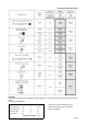
Victrix Zeus 20/27 Instructions Variable Heat Output: Victrix 20: N.B.: Pressure values specified in the table indicate the difference of pressure values between the gas valve outlet and the combustion chamber. Adjustments are carried out using a differential pressure gauge.
Victrix Zeus 20/27 Instructions Victrix Zeus 20/27 Wiring Diagram: Page 21