
Operating instructions


Page 6
Victrix Zeus 20/27 Instructions
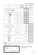
Flue Systems
When the boiler is installed on an external wall, the standard horizontal concentric 60/100 flue kit will normally
be used to flue the boiler. This is shown in the diagram.
It is often necessary to install a longer flue system to cater for site conditions. There are several different flue
system sizes available for the Victrix Zeus 20/27 boiler.
Horizontal concentric kit 60 /100
Install the bend with flange (2) on the central hole of the boiler in-
serting the seal (1) with the round protrusions facing downwards in
contact with boiler flange and tighten using the screws supplied
with the kit.
Fit the smooth male end of the 60/100 concentric terminal pipe (3)
until it reaches to the stop on the female end of the bend (2), mak-
ing sure the internal and external sealing rings are fitted; this will
ensure the connection is properly sealed. Additional extensions
and bends may be installed if required using the same method.
Ensure that all seals are fitted and that the outer and inner pipes
are installed so that all joints are perfectly sealed. Ensure that the
terminal is installed the right way up.
A lubricant may assist in overcoming the friction of the seals. Oils
and conventional greases are not compatible with the EPDM seals
used and should never be used for this purpose. Silicone sprays
are compatible with EPDM and may be used. Please contact RVR
for more information.
A supporting clamp should be installed every three meters. The flue system should be slightly inclined so that
any condensate flows towards the boiler. This avoids any drips from the external flue terminal.
The maximum possible overall length after the first bend (2) is 12.9 straight and horizontal meters. See
the section on extended flue design for more information.
Vertical concentric kit 60 /100
Install the concentric flange (2) on the central hole of the boiler
inserting the seal (1) with the round protrusions facing down-
wards in contact with boiler flange and tighten using the screws
supplied with the kit.
Fit the male end (smooth) of the adapter (3) in the female end of
the concentric flange (2) until it reaches the stop on the female
end of the flange, making sure the internal and external sealing
rings are fitted; this will ensure the connection is properly sealed.
Additional extensions and bends may be installed if required us-
ing the same method.
Installing the flashing- Replace tiles with the aluminium sheet (5),
shaping it to ensure that the rainwater runs off. Position the fixed
half-shell (7) on the aluminium tile and insert the intake/exhaust
pipe (6). Fit the male end (6)(smooth) of the 60/100 concentric
terminal up to the stop on the female end of the adapter(3), mak-
ing sure that the ring (4) is already fitted; this will ensure hold and
joining of the elements making up the kit.
Ensure that all seals are fitted and that the outer and inner pipes
are installed so that all joints are perfectly sealed. A lubricant may
assist in overcoming the friction of the seals. Oils and conventional greases are not compatible with the EPDM
seals used and should never be used for this purpose. Silicone sprays are compatible with EPDM and may be
used. Please contact RVR for more information.
A supporting clamp should be installed every three meters.
The maximum possible overall length including the terminal is 13.4 straight and horizontal meters.
NB: If the terminal or extension pipes need shortening ensure that the inner pipe protrudes by 5mm with
respect to the external pipe.