Mobilemule™ 5 Channel 1080p Mobile DVR with GPS and Live Video Options (HDD) Instruction Manual We strongly advise our clients to monitor our website for notifications and implementing changes as made necessary regarding the above. We also strongly encourage constructive User feedback regarding errors.
Mobilemule™ USING THE USER INTERFACE (UI) The DVR User Interface is designed to be clear, concise, consistent and easy to use for system setup, use and change. All selections and data entries are thru the use of the IR Remote Control (IRC) and the Virtual Keyboard. Read the dedicated pages regarding their use and the operational cues within the Screen Features. User Index USING THE USER INTERFACE (UI) ..................................................................
Mobilemule™ 1.3.4.1 RECORDING SCHEDULE .................................................................. - 29 - 1.3.5.1 SD CARD RECORDING SETUP.......................................................... - 30 - 1.3.6.1 IP CAMERA SETUP.......................................................................... - 31 - 1.3.6.1.1 ADD IP CAMERA .......................................................................... - 32 - 1.3.6.1.2 MODIFY IP CAMERA ......................................................
Mobilemule™ IR REMOTE CONTROL (IRC) FUNCTION KEYS LOGIN NUMBERS PTZ CAMERA DIRECTION ENTER RETURN CANCEL INFO PLAYBACK SPLITSCREEN PTZ ON/OFF TEST NOTE: Insert two new AAA alkaline batteries (User supplied) prior to the first use of the IRC. Function Key Color Code used in the User Guide: ENTRY IRC (Above) function key: Black background with white lettering MDVR Onscreen function key: Blue background with white lettering. A dark blue background appears it is selected by the IRC.
Mobilemule™ IR REMOTE CONTROL USE FOR DATA ENTRY (IRC) NUMBER S DIRECTION ENTER RETURN CANCEL ENGLISH BACKSPACE SHIFT The IR Remote Control (IRC) is used in conjunction with the MDVR Virtual Keyboard to enter alphanumeric data into the MDVR OS selection and data fields. The Virtual Keyboard will automatically appear as needed. Use the IRC Number Keys for Fields requiring numbers only. Types of Data Fields used in the GUI: (DATA FIELD) The MDVR system will post the data.
Mobilemule™ TYPICAL UI PAGE LAYOUT SCREEN ID And NAME FLOWCHART (SYSTEM MAP) PRIOR SCREEN YOU ARE HERE NEXT SCREEN USAGE SUMMARY ITEM NAME AND USAGE ACTION BAR KEYS -6-
Mobilemule™ MENU SCREEN LAYOUT TITLE SCREEN ID TITLE BAR HIGHLIGHTED ICON ICON AREA HIGHLIGHTED ICON CONTENT The 1.1 SETUP MENU screen shown above is an example of a typical UI Menu or sub Menu. The Menu acts as a general gateway to more specific Sub Menus and Data Screens for entering data and the settings of various MDVR functions, features and actions.
Mobilemule™ DATA SCREEN LAYOUT SCREEN ID TITLE TITLE BAR DATA FIELD DATA AREA FIELD NAME ACTION BAR ACTION KEYS The Data Screen enables a User with appropriate authorization to view, setup and change the MDVR UI fields, features and functions.
Mobilemule™ DATA ENTRY AND REPORT FIELDS There are several different types of Data Fields used within the MDVR GUI: SYSTEM FILL DATA ENTRY DATA ALERT DROP DOWN DROP DOWN MENU DATA ENTRY CHECK BOX CHECK AND GO ( ) Data is automatically entered by the MDVR OS (GPS, Month, Measurement Unit, Device Reading, etc.
Mobilemule™ VIDEO SCREEN LAYOUT SPEED RECORDING DATE and TIME VEHICLE ID STORAGE I/O STATUS GPS TEMPERATURE Screen View with Data Overlay Displays current or recorded camera view(s) and/or information (Previously set in the UI) overlaid on video, including System Messages, Alerts and Status.
Mobilemule™ DEVICE START-UP The following assumes the User has confirmed the MDVR is correctly installed according to the manufacturers installation instructions and is correctly configured for use: Pre-check before Startup: LCD MONITOR SECURITY PANEL POWER SOURCE Connected to either the rear I/O Cable Monitor Connector or the A/V Jack on the Front Panel Closed Connected and MDVR STATUS PANEL PWR indicator (blue) is lit Startup Sequence: CHECK POWER INSERT KEY POWER ON The PWR indicator (blue) will be
Mobilemule™ 1.0 INITIAL LOGIN USER LOGIN 1.0 SETUP MENU 1.1 The 1.0 USER LOGIN screen is used to provide secure access to the MDVR settings by requiring User Name and Password entry for access to the MDVR features, functions and settings. For security purposes change original USER NAME and PASSWORD as soon as possible.
Mobilemule™ 1.1 SETUP MENU USER LOGIN 1.0 SETUP MENU 1.1 The 1.
Mobilemule™ 1.1.1.1 DATE AND TIME SETUP MENU 1.1 'GENERAL' GENERAL 1.1.1 'DATE and TIME' DATE and TIME 1.1.1.1 The 1.1.1.1 DATE and TIME screen allows the User to select or enter data to set the System Time and other basic time related properties of the MDVR. DATE TIME (DAY) DATE FORMAT TIME FORMAT TIME ZONE PLUS TIME MODE TIME CHECK MAINT M.
Mobilemule™ 1.1.2.1 VEHICLE SETUP SETUP MENU 1.1 'GENERAL' GENERAL 1.1.2 'VEHICLE INFO' VEHICLE INFO 1.1.2.1 The 1.1.2.1VEHICLE INFO screen is used to enter data and enable functions related to the company, vehicle, driver, mobile phone number and power related operation. The DEVICE NUMBER is the only field required to have data entered. (DEVICE SERIAL ID) DEVICE NUMBER DEPARTMENT DRIVER NAME SIM NUMBER MILE ACCRUAL ODOMETER(MILEAGE) LICENSE PLATE (VEHICLE-NUM) Unique number assigned by factory.
Mobilemule™ 1.1.3.1 USER SETUP SETUP MENU 1.1 'GENERAL' GENERAL 1.1.3 'USER SETUP' USER SETUP 1.1.3.1 The 1.1.3.1 USER SETUP screen allows setup of two levels of Password protected access to the MDVR UI. The ADMIN User account must have at least its Password changed first. Use the Action Bar keys to add, modify or delete User Accounts. After the initial STSTEM (ADMIN) User Account has at least its Password changed and saved it will be necessary to login again using the new Password.
Mobilemule™ 1.1.3.1.1 ADD USER SETUP MENU 1.1 'GENERAL' GENERAL 1.1.3 'USER SETUP' USER SETUP 1.1.3.1 'ADD' ADD USER 1.1.3.1.1 The 1.1.3.1.1 ADD USER screen allows SYSTEM level Users to add SYSTEM (total access) or GENERAL (limited access) level Users for setup and operation of the MDVR User Interface. A total of eight User accounts are allowed. After a User Account is entered and saved it will be necessary to login again using the new Password.
Mobilemule™ 1.1.3.1.2 MODIFY USER SETUP MENU 1.1 'GENERAL' GENERAL 1.1.3 'USER SETUP' USER SETUP 1.1.3.1 'MODIFY' MODIFY USER 1.1.3.1.2 The 1.1.3.1.2 MODIFY USER screen allows SYSTEM level Users to change the parameters of an existing User account. Once the selected User account is added the 1.1.3.1 USER SETUP screen will appear. To modify another User account repeat the Modify User account process.
Mobilemule™ 1.1.3.1.3 DELETE USER SETUP MENU 1.1 'GENERAL' GENERAL 1.1.3 'USER SETUP' SETUP SETUP 1.1.3.1 'DELETE' DELETE USER 1.1.3.1.3 The 1.1.3.1.3 DELETE USER screen allows a SYSTEM level User to delete an existing User account. If a User account is deleted by mistake, it will have to be re-entered using the 1.1.3.1.1 ADD USER screen. Once the selected User account is deleted the 1.1.3.1 USER SETUP screen will appear. To delete another account repeat the Delete User account process.
Mobilemule™ 1.1.4.1 NETWORK SETUP (3G/4G/WIFI Option Required) SETUP MENU 1.1 ' 'GENERAL' GENERAL 1.1.4 'NETWORK' NETWORK SETUP 1.1.4.1 The 1.1.4.1 NETWORK SETUP function enables the User to setup a 3G/4G/WIFI based, full duplex (bi-directional), communication between the MDVR and the Central Monitoring Service (IVMS) (optional) for real time, remote monitoring, setup, speed, etc. To utilize these functions, a compatible Internal or External WIFI Modem or 3G/4G must be connected and enabled.
Mobilemule™ 1.1.5.1 DISPLAY SETUP (PG 1 OF 2) SETUP MENU 1.1 'GENERAL' GENERAL 1.1.5 'DISPLAY' DISPLAY SETUP 1.1.5.1 'NEXT' DISPLAY SETUP 1.1.5.2 The 1.1.5.1 DISPLAY SETUP screen allows the selection of video input (Cameras) and video output (Monitor). If the wrong type is selected for the Camera or Monitor, a horizontal ‘rolling effect’ may be seen.
Mobilemule™ 1.1.5.2 DISPLAY SETUP (PG 2 OF 2) SETUP MENU 1.1 'GENERAL' GENERAL 1.1.5 'DISPLAY' DISPLAY SETUP 1.1.5.1 'NEXT' DISPLAY SETUP 1.1.5.2 The 1.1.5.1 DISPLAY SETUP screen allows to the User to select Embed and/or Overlay options for the fields listed on the screen.
Mobilemule™ 1.1.6.1 CODE OSD SETUP MENU 1.1 ' 'GENERAL' GENERAL 1.1.6 'CODE OSD' CODE OSD SETUP 1.1.6.1 The 1.1.6.1 CODE OSD screen provides the function of character overlay for each video channel, which determines the display position of the characters according to the abscissa and ordinate values. Note: The CH 5 is used for IP cameras connected to the RJ 45 connector, and the IP camera can also set the character overlay function individually.
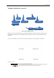
Mobilemule™ 1.2.1 CHANNEL MODE The 1.2.1 CHANNEL MODE screen allows the selection of one of four camera groups to match the variety of AHD, Analog and IP Cameras which may be connected to the MDVR Camera inputs.
Mobilemule™ MIX OPTION 3 MIX OPTION 4 MIX OPTION 5 MIX OPTION 6 MIX OPTION 7 MIX OPTION 8 MIX OPTION 9 AHD Cameras are limited to connection to Camera Input Channels 1 and 2 ANALOG Cameras are limited to connection to Camera Input Channels 3 and 4 AHD Cameras may be connected to Camera Input Channels 1, 2, 3, 4 IP Camera may be connected to the RJ45 Port ANALOG Cameras may be connected to Camera Input Channels 1, 2, 3, 4 IP Camera may be connected to the RJ45 Port Only AHD Cameras may be connected to Ca
Mobilemule™ 1.3.1.1 RECORD SETUP SETUP MENU 1.3 'RECORD' RECORD MENU 1.3.1 'RECORD' RECORD SETUP 1.3.1.1 The 1.3.1.1 RECORD SETUP screen is one of the most used setup screens concerning file storage criteria. RECORD TYPE RECORD MODE PACKET TIME(REC LENGTH) OVERWRITE PRERECORD POST RECORD(ALM DELAY) ALM OUT ALM FILE LOCK ENCRYPT VID ENCRYPT KEY DISPLAY AUD OUT VOL ACC/REC OFF UPLOAD VIDEO(NORMAL) Records video per settings in 1.3.2.
Mobilemule™ 1.3.2.1 MAIN CODE SETUP MENU 1.3 'RECORDING' RECORD 1.3.2 'MAIN CODE' MAIN CODE 1.3.2.1 The 1.3.2.1 MAIN CODE screen provides the ability to configure each of the MDVRs five video channels to provide the optimum balance of Video Type, Frames per Second (FPS), Resolution and Quality while ensuring the maximum file storage is achieved on the installed storage media. NOTE: CH 5 is for the IP Camera connected to the RJ 45 connector.
Mobilemule™ 1.3.3.1 SUB – STREAM SETUP SETUP MENU 1.3 'RECORD' RECORD 1.3.3 'SUB-STREAM' SUB-STREAM SETUP 1.3.3.1 The 1.3.3.1SUB-STREAM SETUP Menu allows the User to achieve a balance between speed of data transmission and the video resolution (clarity). The uploading (transmission) of the video files from the MDVR to another location by WIFI or 3G cellular communication networks is limited by Bandwidth.
Mobilemule™ 1.3.4.1 RECORDING SCHEDULE SETUP MENU 1.3 'RECORD' RECORD 1.3.4 'RECORDING SCHEDULE' RECORDING SCHEDULE 1.3.4.1 The 1.3.4.1 RECORDING SCHEDULE screen allows the MDVR to be programmed to record for two periods per day. The default setting is to record whenever the MDVR is operating. It can also be set to use the same recording periods every day or each day can be set to record using a schedule specific to that day.
Mobilemule™ 1.3.5.1 SD CARD RECORDING SETUP SETUP MENU 1.3 'RECORD' RECORD 1.3.5 'SD REC' SD CARD RECORDING 1.3.5.1 The 1.3.5.1 SD CARD RECORDING screen allows the User to enable the MDVR to save recorded files to the SD Card. Enabling SD Card Recording does not effect the settings for the HDD.
Mobilemule™ 1.3.6.1 IP CAMERA SETUP SETUP MENU 1.3 'RECORD' RECORD 1.3.6 'IP CAMERA' IP CAMERA 1.3.6.1 The 1.3.6.1 IP CAMERA SETUP screen allows the detection and setup of an IP Camera using the MDVR RJ 45 Port. Once an IP Camera is connected to the RJ 45 Port it is automatically discoverable by the MDVR. Initial IP Camera setup: GO TO RETURN ADD 1.2.1 CHANNEL MODE screen and complete the CHANNEL setup.
Mobilemule™ 1.3.6.1.1 ADD IP CAMERA SETUP MENU 1.3 'RECORD' RECORD 1.3.6 'IP CAMERA' IP CAMERA 1.3.6.1.1 'ADD' ADD IP CAMERA 1.3.6.1.1 The 1.3.6.1.1 ADD IP CAMERA screen allows authorized Users to add and search for connected IP Cameras.
Mobilemule™ 1.3.6.1.2 MODIFY IP CAMERA SETUP MENU 1.3 'RECORD' RECORD 1.3.6 'IP CAMERA' IP CAMERA 1.3.6.1 'MODIFY' MODIFY IP CAMERA 1.3.6.1.2 The 1.3.6.1.2 MODIFY IP CAMERA screen allows authorized Users to change the parameters of an existing IP Camera. This is useful for filling in the data fields when the auto fill feature is not available.
Mobilemule™ 1.3.6.1.3 DELETE IP CAMERA SETUP MENU 1.3 'RECORD' RECORD 1.3.6 'IP CAMERA' IP CAMERA 1.3.6.1 'DELETE' DELETE IP CAMERA 1.3.6.1.3 The 1.3.6.1IP CAMERA SETUP screen allows an authorized User to delete an existing IP Camera. After DELETE has been selected and entered, a System Warning Message ‘DELETE THIS IP CAMERA?’ will be appear onscreen. Select from two options: CANAEL OK Cancel deletion. Select and press ENTER to cancel deletion and return to the 1.3.6.
Mobilemule™ 1.4.1.1 SENSOR SETUP SETUP MENU 1.4 'ALARMS' ALARM SETUP 1.4.1 'SENSORS' SENSOR SETUP 1.4.1.1 The 1.4.1.1 SENSOR SETUP screen defines the trigger response relationship between each of the 8 Sensor In (Inputs) and actions available.
Mobilemule™ 1.4.2.1 SPEED SETUP SETUP MENU 1.4 'ALARMS' ALARM SETUP 1.4.2 'SPEED' SPEED SETUP 1.4.2.1 The 1.4.2.1 SPEED SETUP screen allows the User to trigger the MDVRs Recording Mode based on low and high speed thresholds determined by the settings entered. Either or both High and Low settings may be entered independently. Vehicle speed can be monitored and recorded using the speed data (KPH or MPH) from either the onboard GPS (optional) or a more accurate speedometer sensor (optional).
Mobilemule™ 1.4.3.1 G SENSOR SETUP SETUP MENU 1.4 'ALARM' ALARM SETUP 1.4.3 'G SENSOR' G SENSOR SETUP 1.4.3.1 The 1.4.3.1 G SENSOR SETUP screen (accelerometer) enables the MDVR to monitor the movement of the vehicle in 3 Axes (X, Y, Z) and can be used to trigger a response based on the Trigger values set in the G Sensor Menu. Readings from the sensor may indicate hard braking, acceleration, impact, sharp turns, etc.
Mobilemule™ 1.4.4.1 TEMPERATURE SETTINGS SETUP MENU 1.4 'ALARM' ALARM 1.4.1 'TEMPERATURE' TEMPERATURE 1.4.4.1 The 1.4.4.1TEMPERATURE SETUP screen allows the User to trigger the MDVRs Recording Mode based on low and high temperature thresholds determined by temperature settings entered. Either or both High and Low settings may be entered independently.
Mobilemule™ 1.4.5.1 ALARM OUT SETUP SETUP MENU 1.4 ''ALARM' ALARM 1.4.5 'ALARM OUT' ALARM OUT SETUP 1.4.5.1 The 1.4.5.1 ALARM OUT SETUP screen defines the Input – Trigger – Response relationships with the various sensors and reporting devices connected to the MDVR. The ALARM OUT SETUP screen adds the ability to add ALARM and ALARM logging responses to the other criteria set within the individual Sensor and Device screens.
Mobilemule™ 1.4.6.1 MOTION DETECTION SETUP MENU 1.4 'ALARM' ALARM 1.4.6 'MOTION' MOTION DETECTION 1.4.6.1 'ALARM OUT SETUP' ALARM OUT SETUP 1.4.5.1 The 1.4.6.1 MOTION DETECTION screen is the first of three screens necessary for the setup, activation and testing of the motion detection features for each camera channel.
Mobilemule™ 1.4.6.1.1 MOTION DETECTION SETUP GRID SETUP MENU 1.4 'ALARM' ALARM 1.4.6 'MOTION' MOTION DETECTION 1.4.6.1 'SETUP' MOTION DETECTION SETUP GRID 1.4.6.1.1 CURSOR NO DETECTION DETECTION The 1.4.6.1.1 MOTION DETECTION GRID is the second of three screens required to setup and test the Motion Detection function. It allows the user to define a detection zone to automatically trigger the functions set in the 1.4.6.1 MOTION DETECTION SETUP and the 1.4.5.1 ALARM OUT SETUP screen.
Mobilemule™ 1.4.7.1 OTHER ALARMS SETUP MENU 1.4 'ALARM' ALARM SETUP 1.4.7 'OTHER ALARMS' OTHER ALARMS 1.4.7.1 The 1.4.7.1 OTHER ALARMS screen allows the IVMS to monitor Driver (Vehicle) activity by monitoring the time elapsed alarms for each field. ACC TIMEOUT (TIMEOUT PARK) Select the length of time before and alarm is sent and logged.
Mobilemule™ 1.5.1.1 CONFIGURATION SETUP MENU 1.5 'TOOLS' TOOLS 1.5.1 'CONFIGURE' CONFIGURE 1.5.1.1 'CONFIGURATION' The 1.5.1.1CONFIGURATION screen allows the user to copy the basic system settings from one MDVR and transfer (Export) them to another MDVR using an USB flash drives. EXPORT CONFIG FILE Select to copy this MDVRs system settings to an USB flash drives for use as backup or to easily setup another MDVR: 1. Insert the USB flash drives on the front panel 2. Select EXPORT CONFIG FILE button 3.
Mobilemule™ 1.5.2.1 FORMAT STORAGE MEDIA SETUP MENU 1.5 'TOOLS' TOOLS 1.5.2 'FORMAT' FORMAT 1.5.2.1 The 1.5.2.1 FORMAT screen allows the User to format Storage Media a (HDD, SSD or SD Card) prior to its initial use or to reformat (erase) a previously used (recorded on) for reuse. Use only name brand SD Cards rated Class 10 or better.Use only an SV rated, EXT3 formatted HDD/SSD in the Drive Tray.
Mobilemule™ 1.5.3.1 SEARCH SYSTEM and ALARM LOGS SETUP MENU 1.5 'TOOLS' TOOLS 1.5.3 'LOG' SEARCH ALARM and SYSTEM LOGS 1.5.3.1 'SEARCH' SEARCH LOG LIST 1.5.3.1.1 The SEARCH SYSTEM and ALARM LOGS Menu allows the user to search all logged events or to search for specific predetermined events the MDVR previously recorded on the installed HDD or SD Card. The colored grid shown lists the days of the search month. To expedite file searches Days with recordings available have a green background.
Mobilemule™ 1.5.3.1.1 SEARCH LOG LIST SETUP MENU 1.5 'TOOLS' TOOLS 1.5.3 'LOGS' SEARCH SYSTEM and ALARM LOGS 1.5.3.1 'SEARCH' SEARCH LOG LIST 1.5.3.1.1 The 1.5.3.1.1 SEARCH LOG LIST allows the user to view the results of the search criteria entered on the 1.5.3.1 SEARCH SYSTEM and ALARM LOGS screen. Use the Action Bar keys to navigate the list.
4 Channels HDD MDVR (720P) USER GUIDE V6.0 (DRAFT) 1.6.1.1 PTZ CAMERA SETUP SETUP MENU 1.6 'PERIPHERALS' PERIPHERALS SETUP 1.6.1 'PTZ SETUP' PTZ SETUP 1.6.1.1 The 1.6.1.1 PTZ CAMERA SETUP screen allows up to four PTZ (Pan, Tilt, Zoom) Cameras to be programmed, viewed and controlled by the MDVR using its IR Remote Control (IRC) or a compatible PTZ Joystick Control Console. Read the manual supplied by the PTZ Cameras manufacturer. Set the operational codes on the camera as required.
4 Channels HDD MDVR (720P) USER GUIDE V6.0 (DRAFT) 1.6.2.1 WIRELESS SETUP SETUP MENU 1.6 'PERIPHERALS' PERIPHERALS 1.6.2 'WIRELESS SETUP' WIRELESS SETUP 1.6.2.1 The 1.6.2.1WIRELESS SETUP screen allows the setup of the (optional) Cellular communications capability of the MDVR allowing real time cellular communication between the MDVR and the IVMS using a carrier compatible SIM Card (Second Card option available) and the Cellular Communication Option installed.
4 Channels HDD MDVR (720P) USER GUIDE V6.0 (DRAFT) 1.6.3.1 WIFI SETUP (Optional module required) SETUP MENU 1.6 'PERIPHERALS' PERIPHERALS 1.6.3 'WIFI SETUP' WIFI SETUP 1.6.3.1 The WIFI SETUP Menu allows the setup of the optional WIFI communications capability of the MDVR allowing real time WIFI communication between the MDVR and the IVMS using either an (optional) internal or external WIFI (802.11n or AC) Modem.
4 Channels HDD MDVR (720P) USER GUIDE V6.0 (DRAFT) 1.6.4.1 FUEL SETUP SETUP MENU 1.6 'PERIPHERALS' PERIPHERALS 1.6.4 'FUEL' FUEL SETUP 1.6.4.1 The 1.6.4.1 FUEL SETUP Menu allows the user to track and record fuel (or other transported fluids) usage or delivery. The use of this feature requires an optional Fuel Sensor connecting via RS 232 or RS 485.
4 Channels HDD MDVR (720P) USER GUIDE V6.0 (DRAFT) 1.6.5.1 SERIAL DEVICE SETUP SETUP MENU 1.6 'PERIPHERALS' PERIPHERALS 1.6.5 'SERIAL'' SERIAL DEVICE SETUP 1.6.5.1 The 1.6.5.1 SERIAL DEVICE SETUP screen allows up to two RS 232 data or control devices to be setup using industry standard RS 232 code settings.
4 Channels HDD MDVR (720P) USER GUIDE V6.0 (DRAFT) 1.7.1 SEARCH RECORDINGS SETUP MENU 1.7 'SEARCH' SEARCH 1.7 'SEARCH RECORDINGS' SEARCH RECORDINGS 1.7.1 'SEARCH' SEARCH PLAYBACK LIST 1.7.1.1 The 1.7.1 SEARCH RECORDINGS screen allows the user to search by Date, Path (Storage Media) and Type (ALL, GENERAL or ALARM) list all recorded events or to search for specific predetermined events the MDVR previously recorded on the installed storage media Path.
4 Channels HDD MDVR (720P) USER GUIDE V6.0 (DRAFT) 1.7.1.1 SEARCH PLAYBACK LIST SETUP MENU 1.7 'SEARCH' SEARCH 1.7 'SEARCH RECORDINGS' SEARCH RECORDINGS 1.7.1 'SEARCH' SEARCH PLAYBACK LIST 1.7.1.1 'ENTER' The 1.7.1.1 SEARCH PLAYBACK LIST displays the results of the last 1.7.1 SEARCH RECORDINGS screen. Select the file or files. To Playback the recorded file(s) selected above use the instructions on the following page.
4 Channels HDD MDVR (720P) USER GUIDE V6.0 (DRAFT) 1.7.1.1 VIEWING FILES Two options to return to the 1.7.1.1 SEARCH PLAYBACK LIST screen VIEW FILE Once the file is completely played the 1.7.1.1 SEARCH PLAYBACK LIST screen will be displayed and the last viewed selection highlighted. RETURN Press to end viewing and return to the 1.7.1.1 SEARCH PLAYBACK LIST screen IRC Playback Related Keys: PLAY Starts Playback of the selected recorded file.
4 Channels HDD MDVR (720P) USER GUIDE V6.0 (DRAFT) 1.8.1 SYSTEM INFO, PG 1 OF 2 SETUP MENU 1.8 'SYSTEM INFO' SYSTEM INFO 1.8.1 SYSTEM INFO PG 2 'NEXT' The 1.8.1 SYSTEM INFO screen is one of two sequential screens to display the current MDVR system settings, real time operational status and optional business contact information. A compatible monitor must be properly connected and configured to either of the MDVR Rear or Front Monitor ports.
4 Channels HDD MDVR (720P) USER GUIDE V6.0 (DRAFT) 1.8.2 SYSTEM INFO, PG 2 SETUP MENU 1.8 'SYSTEM INFO' SYSTEM INFO PG 1 'NEXT' SYSTEM INFO PG 2 'NEXT' The1.8.2 SYSTEM INFO screen shown above is Page 1 of 2 sequential screens displaying the current MDVR system settings, operational status and business contact information. To view the INFO screen: Press to view PG 1 of the System Info screens. INFO Press to return to the previous page RETURN Note: For Status Report purposes only. No User entries.