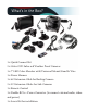
What’s in the Box? 1 x Quick Connect Kit 2 x Color CCD Infra-red Weather Proof Cameras 1 x 7" LED Color Monitor with/Universal Mount/Stand & Wire 1 x Power Harness 1 x 66’ Extension Cable for Backup Camera 2 x 33’ Extension Cables for Side Cameras 1 x Remote Control 1 x Double RCA + Power Converter (to connect external audio, video and power) 1 x Screw Kit for installation
Table of Contents Introduction ...................................................................................................4 Safety Information ..................................................................................5-7 Before Beginning Installation...................................................................8 Installation Guide.........................................................................................9 Wiring Camera & Monitor..........................................
Introduction Please read all of the installation instructions carefully before installing the product. Improper installation will void manufacturer’s warranty. Congratulations on purchasing a Rear View Backup Camera System! With this manual you will be able to properly install and operate the unit. The Backup Camera System is intended to be installed as a supplement aid to your standard rear view mirror that already ex- ists in your vehicle.
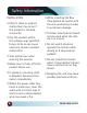
Safety Information Please read the entire manual and follow the instructions and warnings carefully. Failure to do so can cause serious damage and/or injury, including loss of life. Be sure to obey all applicable local traffic and motor vehicle regulations as it pertains to this product. Improper installation will void manufacturer’s warranty. USAGE • The Rear View Camera System is designed to help the driver safely detect people and/or objects helping to avoid damage or injury.
Safety Information INSTALLATION • Electric shock or product malfunction may occur if this product is installed incorrectly. • Use this product within the voltage range specified. Failure to do so can cause electronic shock or product malfunction. • Take special care when cleaning the monitor. • Make sure to firmly affix the product before use. • If smoke or a burning smell is detected, disconnect the system immediately.
Safety Information If you have questions about this product, contact: Customer Service: Rear View Safety 1797 Atlantic Avenue Brooklyn, NY 11233 Tel: 1.800.764.1028 IN NO EVENT SHALL SELLER OR MANUFACTURER BE LIABLE FOR ANY DIRECT OR CONSEQUENTIAL DAMAGES OF ANY NATURE, OR LOSSES OR EXPENSES RESULTING FROM ANY DEFECTIVE PRODUCT OR THE USE OF ANY PRODUCT.
Before Beginning Installation Before drilling please check that no cable or wiring is on the other side of the wall. Please clamp all wires securely to reduce the possibility of them being damaged while vehicle is in use. Keep all cables away from hot or moving parts and electrical noisy components. We recommend doing a benchmark test before installation to insure that all components are working properly. Step 1: Choose the monitor and camera locations.
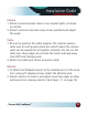
Installation Guide Camera 1. Attach camera bracket close to rear marker lights, centered on vehicle. 2. Attach camera to bracket using screws provided and adjust the angle. Cable 1. Be sure to position the cable properly. The aviation camera cable uses aircraft grade connectors which means the camera cable can be exposed to all weather elements. Do not run the cable over sharp edges, do not kink the cable and keep away from HOT and rotating parts. 2. Fasten all cables and secure all excess cable.
Wiring Camera & Monitor • To power the system connect the power (RED) 12V+ wire to ignition power and the ground (BLACK) wire to chassis ground. • These are the only wires needed to power the entire system and all the cameras. Each camera can be seen at any time by simply pressing the power button and using the V1/2 button to toggle. • The three positive trigger wires (BLUE-CH1, WHITE-CH2, YELLOW-CH3) each represent one channel and will turn on their channel when the trigger wire is energized with 12V.
Wiring Camera & Monitor • Audio: There is audio on channels 2 and 3. On channel 3 the blue trigger wire must be energized (12V) to activate the audio. On channel 2 the audio is always on. • Grid-lines: The grid-lines are also carried through the blue wire. To use the grid-lines for reversing, connect the blue wire to a reverse power. • There is a built-in voltage regulator for our systems which can handle 9-32 volts. Real consumption is 10 to 30 Volts.
The Quick Connect The Quick Connect: The Quick Connect is designed so you can connect your camera system with utmost ease when hitching your trailer. Here is a description of how the system works and how it is set up. 1. The cabling on this system is split into three parts, two camera cables that end with Quick Connect terminals and a Pigtail Cable. 2. The first camera cable (26') mounts on the tow vehicle.
Installation Diagram Figure 1.1 Figure 1.2 Figure 1.3 Figure 1.
General Wiring 14 REAR VIEW SAFETY
Monitor Operation DOWN ARROW CAMERA SELECTION MENU/ UP ARROW SELECTION BUTTON POWER ON / OFF V1/V2 ▼ ▼ MENU REV ROTATE IMAGE (Back/Exit when in Menu Mode) • • • • • • • • • Brightness, Contrast, Saturation, Sharpness: adjust image properties Turn: Toggle between mirror/normal image on each individual channel Day/Night: Toggle between back-lit buttons and auto dimming Name: Change name of each individual channel Trigger Source: Toggle channel destination for each trigger Trigger Delay: Adjust tim
Splitting & Splicing Installing sun shield: Put shade cover on the display. Installing back cover: Put the monitor with shade cover in the back cover (only for embedded monitor) Splitting back cover: Hold monitor with 2 hands and detach with fingers, as indicated by arrows. (only for embedded monitor) Splitting sun shield: Take the monitor with the left hand and detach with right hand as indicated by the white arrow. (see below) 1. 2. 3. 4. 5. 1. Red - Power (+) 2. Yellow - Video 3.
Positioning Reverse With Confidence™ 17
Monitor Dimensions 7” Rotation Imager Menu/ Camera Down Up (Exit in Power Selection Selection ArrowArrow Menu Mode) On/Off Button 5.
Monitor Specifications LED Digital Monitor Screen Size 7” Display Format 16:9 / 500:1 Dot Resolution Display Brightness Viewing Angle Video Input Video Source 400cd/m2 U:50° / D:60° / R:70° 3 channel 1Vp-p, 75Ω Power Supply DC 9V-32V Storage Temperature -30°C~+85°C Video System NTSC/PAL Weight 400G Operating Temperature Overall Dimensions -20°C ~ +70° C Auto 7”L x 5.25”H x 1”D Impact Rating 5G Sync System Internal Dot Pitch 19 800H x 3 (RGB) 480V 0.1926H x 0.
Rear Camera Dimensions Rear Camera 3” 3.
Camera Specifications Camera 1/3” Sharp® Color CCD Picture Elements 410,000 pixels Gamma Correction r=0.45 to 1.0 Image Sensor 620TVL NTSC: 811H x 507V PAL: 752H x 582V Lens 2.5mm View Angle 130° Sync System Infrared distance Internal Synchronization 50 Feet (18 Infrared IR) Usable Illumination 0 Lux (IR On) Power Source DC 9V-32V S/N Ratio Electronic Iris More than 48dB 1/50, 1/60-1/100,000sec Video Output 1Vp.
Side Camera Dimensions Side Camera Reverse With Confi- 22
Side Camera Specifications Side Camera 1/4” Sharp® Color CCD Gamma Correction r=0.45 to 1.0 420 TV Lines Picture Elements Image Sensor Lens View Angle 250,000 pixels PAL:500h x 582v, NTSC: 510h x 492v 2.
Troubleshooting Monitor Displays Blue Screen & Displays No Signal • Do a hard reset, unplug all cables and power cables from multiplexer (silver box) leave out for 1 minute and then re-connect them. • Check to ensure that the connection to the camera is tight. • Verify camera cable is plugged into port labeled Backup Camera • Verify that the blue positive trigger on power harness is put to power 12v+. If the problem still persists, verify that alternate ports work.
Warranty One Year Warranty Rear View Safety Inc. warrants this product against material defects for a period of one year from date of purchase. We reserve the right to repair or replace any such defective unit at our sole discretion. Rear View Safety Inc. is not responsible for a defect in the system as a result of misuse, improper installation, damage or mis-handling of the electronic components. Rear View Safety Inc. is not responsible for consequential damages of any kind.
Disclaimer Rear View Safety and/or its affiliates does not guarantee or promise that the user of our systems will not be in/part of an accident or otherwise not collide with an object and/or person. Our systems are not a substitute for careful and cautious driving or for the consistent adherence to all applicable traffic laws and motor vehicle safety regulations. The Rear View Safety products are not a substitute for rearview mirrors or for any other motor vehicle equipment mandated by law.
table of contents If you have any questions about this product, contact: Rear View Safety, Inc. 1797 Atlantic Avenue Brooklyn, NY 11233 800.764.1028 BETTER CAMERAS. BETTER SERVICE. IT’S OUR GUARANTEE.