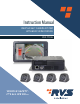
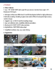
Instruction Manual 1080P HD 360° CAMERA SYSTEM WITH BUILT-IN RECORDING RVS-77555 VEHICLE SAFETY IT'S ALL WE DO.
Table of Contents 1. Precautions....................................................................................................................... 3 2. Features............................................................................................................................ 5 3. Standard Configuration................................................................................................... 6 4. Specifications............................................................................
1. Precautions Storage and Keeping 1. Do not expose the System to excessive heat or cold. The storage temperature of this device is -30~+80°C, and the operating temperature is -20~+70 °C. The humidity is RH 90%. 2. Never use this device near a bathtub, wash basin, kitchen, damp basement, swimming pool or similar places. 3. Never use this device in environments with excessive moisture, dust or smoke. 4. Avoid dropping or striking this device. 5.
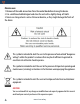
Maintenance 1. Remove all the cable connections from the control box before cleaning the device. 2. Use a mild household detergent and clean the unit with a slightly damp, soft cloth. 3. Never use strong solvents such as thinner or benzine, as they might damage the finish of the device. This symbol is intended to alert the user to the presence of uninsulated "dangerous voltage" within the product's enclosure that may be of sufficient magnitude to constitute risk of electric shock to persons.
2. Features 2.1 Basic Features 1. 4 pcs. 190° Full HD 1080P wide-angle fish-eye cameras, horizontal view angle>170°, Maximum of 8CH inputs. 2. Techniques of dual-core ARM Cotex-A9 and SOC development of built-in high performance H.264 video encoding / decoding engineer core make it efficient to composite high accuracy seamless images. 3. Supports 4 pcs. x 128G SD cards for recording storage. 4. Low-cost calibration tools, simplified calibration procedures. 5. Maximum 4CH 1080P / 30 FPS video resolution. 6.
2.3 Features 1. Panoramic image. 2. Blending seamless stitching. 3. 360° view. 4. Auto switch to reversing image when reverse wire is triggered. 5. Auto switch to left / right image when left / right wire is triggered. 6. Installation guide with pictures. 7. Automatic plane correction. 8. Supports Recording. 3.
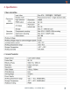
4. Specifications 1. Main Control Box 2. Camera Parameter Vehicle Safety - It's All We Do.
5.
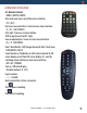
6.Operation Instruction 6.1 Remote Control • MENU: (ENTER / MENU) Enter into main menu or confirm menu selection. • SYS: (ESC) Exit main menu interface / return to main menu interface. • V- / V+: (LEFT, RIGHT) Left, right / Decrease, Increase button. Shift image channel to left / right view, or operate plus / minus in main menu interface. • P+ / P-: (UP, DOWN) Front / back button. Shift image channel to front / back view.
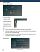
6.2 User Interface 6.2.1 User Administration Feature Description: 1) Input password. 2) Login confirmation. 3) Change Password 4) Return to last menu Note: 1) Initial password: 000000. Please modify password after stitching is finished. 2) If password is forgotten, input “root” to log in. Select factory default setting in Information menu and new password will be 000000 3) The operation period lasts for 10 min after login.
Setting Description: 1) Current password 2) New Password 3) Input new password again 4) Save password 5) Return to last menu 6.2.2 Main menu interface Feature Description: 1) 2) 3) 4) 5) 6) 7) 8) System: Basic function setting. Clock: System time setting. Storage: Storage function and system log management. DVR: Recording function configuration. AVM: 360 panorama calibration and related operation. Player: Video file playback and processing. Information: Upgrade operation and local IP setting.
6.2.3 System Setup Feature Description: 1) Standby Delay: Time frame can be set for standby. 2) AV: PAL / NTSC .Correspondent video output format is 1080P / 50 frames or 1080P / 60 frames. 3) Full Panel AVS: Button for full screen / panoramic display. Temporarily unavailable. 4) Surround View Region: Surround view size selection. 5) Language: Language setting. Temporarily unavailable. 6) Slow Wake up: Button for wake up in slow speed. Temporarily unavailable.
6.2.4 Clock Setup Feature Description: 1) 2) 3) Set calendar time. Save setup time. Exit menu and return to the main menu. Menu setting change must be saved to become 6.2.5 Storage Feature Description: Format SD Card or U Disk. 1) 2) Select all system log files Vehicle Safety - It's All We Do.
3) 4) 5) 6) Unselect all system log files. Clear all old system log files. Export the selected system log file. Exit the Storage interface and return to the main menu. Note 1) When the U Disk and SD Card work abnormally, there will be a cursor prompt on the panorama display interface and Storage menu interface. See the Storage State menu under the Storage Menu for specific error reasons.
4) 5) 6) Power on automatic video recording function setting. Save setting parameters. Exit the DVR interface and return to the main menu. If any parameter is modified, it must be saved before exit, otherwise the modification is invalid. Note: When parameters are modified, saving or exit will prompt to restart. 6.2.7 AVM Calibration Feature Description: 1) Length / Width / Chess Position / Grid Size: Panoramic stitching parameters. 2) Enter chessboard setting. 3) Enter image stitching menu.
Soft Keyboard Feature Description: 1) Exit editing. Delete input. 2) Capital shift. 3) Letter lock. 4) Note: 1) Letter lock is locked by default. Unlock to input characters. 2) Letter can only be input via soft keyboard. Chess Board Feature Description: 1) Layout setting of calibration cloth. 2) Save. Note: Layout setting should be compliant with real calibration cloth.
AVM Option Setup Feature Description: 1) Upload calibration files of U Disk to system. 2) Output saved calibration files and 4CH single-view to U Disk. 3) 4) Change vehicle models. Exit Key: Get back to AVM Calibrate interface. Note: Calibration file applies XML extension. Vehicle Safety - It's All We Do.
Upload Calibration Files Feature Description: 1) 2) Select uploaded files with XML extension. Confirm selected files with XML extension. Note: If the preference of uploaded file is empty, please select files with XML extension from the expand list. Once the change of XML files confirms, you are to be prompted to restart the system either save or exit.
Setting Description: Confirm output files. 1) Note: 1) Before output, make sure U Disk is connected and functioning normally. U Disk shouldn't be pulled out during processing. 2) After successfully output files, name it with the time and date of the system. Change Vehicle Models Feature Description: 1) Select vehicle models. (Left to right: user-defined vehicle models, bus model, truck model, car model.) 2) 3) User-defined vehicle model picture. Save selected vehicle model.
6.2.8 Player Interface Feature Description: 1) Calendar list: Green highlighted dates represent video files of current date. Press return key to get back to player interface. 2) Time list: Green represents video files of current time. Press cancel key to get back to calendar 3) Video list and control key: All / none / delete / export / play key to operate video settings.
Note: 1) If the system is recording video, you will be prompted to close the recording before entering player. Please note the timing for player. Recording will be automatically recovered once exits the player. 2) System can only search and play videos recorded 3 months before the system's current date. Playback Interface Feature Description: 1) Control button and progress bar for playback. Note: 1) Page Up / Page Down can only switch playback videos among the selected.
6.2.9 Information 1) APP Version: Current APP Flash version information / upgrade files list / upgrade confirmation key. This function is activated only when there's APP upgrade file HD360-CPU-APP-00-Vx.x.xx.tar.gz under U Disk root file. 2) Firmware Version: Current MCU Firmware version information / upgrade files list / upgrade confirmation key. This function is activated only when there's MCU upgrade file HD360-MCU-APP-00-Vx.x.xx.bin under U Disk root file.
6.2.10 Radar Setup 1) Channel and Sensors: Each channel uses 3 sensors. Red sign flickers when sensor detects any obstacle in the range. If combine-select currently edited locations of radar sensor, their represented red blocks will flicker. 2) Select on to enable sensor to work and off to disable. Detection range is configurable from 0.6m to 5m. Save settings of selected radar sensors. 3) Restore to the initial default setting. 4) Exit to get back to main menu.
Tips for Installation and Calibration of 360 System 1. The mats need to match with the vehicle size. For example, the vans or other similar-sized/smaller-sized vehicles should be calibrated with the 20CM chess-board mats. The trucks or similar-sized/larger-sized vehicles should be calibrated with the 40CM chess-board mats. If the larger 40CM mats are used for smaller-sized such as vans, please try to lift the camera installation position up to make it capture more views. 2.
7. System Contents Control box Camera Power Cable Main Wire Bundle IR Extension Cable Camera Extension Cable Remote Control 1080P HD Monitor HDMI Adapter Cable WEBAPP Transmitter Vehicle Safety - It's All We Do.
8. Installation Steps Step 1: Wiring • Start wiring from the camera to the main unit of 360 system; • The main unit is usually put in the central control room or behind the tool box. Step 2: Installing cameras • Choose proper camera position • Drill holes that fit the size of regular assemblies. • Fix the front housing 26 Rear View Safety • Fix the back and front housing together.
Step 3: Installing Cameras • Adjust camera angle one by one. Then screw it tightly. • Make sure the original image mark (white dot on cameras) are placed outward; • Proper angle of cameras Vehicle Safety - It's All We Do.
Step 4: Install the main unit • The main unit is usually put in the central control room or behind the tool box. Step 5: Check the wiring connection before powering on • Make sure all cables are well connected before powering on. Step 6: Check basic function of the system • Images from 4 cameras can be displayed on the screen • Surround view is on the left and single view on the right • Single view could be switched by remote if needed.
Step 2: Lay calibration mats • Make sure each mat could be completely shown in the according single view. • Mats in the front/back should be laid in the middle as the front/back cameras are mostly installed in the middle. • While position of the mats in the right/left can be adjusted, as long as the mats are completely shown in the image, it is suggested to put middle point of the mat just below the camera.
Step 3: Enter “AVM calibrate” • Input calibration figures of Length, width, cheese position (in cm); • Grid size is 40 cm by default for large vehicle system, 20 cm by default for small vehicle system. You could also use other mats and set up the grid size accordingly; • Enter chess board interface to check whether figures are the same as the grid numbers of the mats. That is “grid (black + white) number at long side” x “number at short side”).
Step 4: Indicating information • On the bottom of the screen, info will be shown indicating the calibration state; • For every channel, there are 3 states: 1) Three Chess board found, calibrate one step, 2) One chess board found, calibrate exit only, 3) No chess board found.
Calibration Mat Chosen and Laid 32 Rear View Safety
Calibration Mat Chosen and Laid (Continued Table 1) Vehicle Safety - It's All We Do.
Calibration Mat Chosen and Laid (Continued Table 2) 34 Rear View Safety
9. WebAPP Operating Instructions 9.1 Preparation • 360 control has internal wifi, and wifi antenna is connected. • This Web UI function does not support IOS system, please use mobile phone with android system to access. • Access must be done using the Google browser. Because this Web UI is developed based on the rendering engine of Google browser, some built-in phone browsers or other types of browsers may not support the responsive function well. 9.
9.3 Features 9.3.1 Video Files Download Feature Description: 1) Select the "+" or "-" icon at the far right of the menu bar to open or close the video download page. 2) Calendar list: Yellow highlighted dates represent video files of current date. Only dates in yellow could be selected. Also dates could be switched by clicking the ">" or "<"icon. 3) Time list: Yellow represents video files of current time.
4) 5) 6) Retrieve all valid video files for the selected time period. Select all video files in the list. Download all selected video files. Note: 1) The download function is only available when there is video file in the 360 round view system. In other words, the SD card must be inserted and there is video file in the SD card. 9.3.2 System Setup 1) Select the corresponding configuration in the system, and click the submit button at the bottom of the page to submit the configuration.
9.3.3 AVM Calibrate Feature Description: 1) Panorama stitching parameter settings. This function is equal to the “AVM Calibrate” interface on the system interface.
9.3.4 DVR Setup Feature Description: 1) “DVR Setup” interface. Recording function related settings. The function is equal to the system’s 9.3.4 Version Import And Export Vehicle Safety - It's All We Do.
FAQs Q1: After the stitching, why don't certain area in front / back / left / right area show any image? 1. Please make sure the calibration lines and cloths are laid properly. 2. Press up / down / left / right button to shift single-view channel and make sure that all cameras are functioning normally and surrounding landscapes don't turn upside down or left / right reversion. Q2: Part of images can't be seamlessly stitched. It's usually caused by accumulative errors.
NOTES Vehicle Safety - It's All We Do.
If you have any questions about this product, contact: Rear View Safety, Inc. 1797 Atlantic Avenue Brooklyn, NY 11233 800.764.1028 Vehicle Safety - It's All We Do.