A Safe Fleet Brand Instruction Manual G-SERIES Backup Camera System with Navigation and Bluetooth RVS-776718-NAVBT Reverse With Confidence ™ Rear View Safety, Inc.
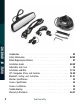
TABLE OF CONTENTS Introduction. . . . . . . . . . . . . . . . . . . . . . . . . . . . . . . 03 Safety Information. . . . . . . . . . . . . . . . . . . . . . . . . . 04-06 Before Beginning Installation . . . . . . . . . . . . . . . . . . . . . . . 07 Installation Guide. . . . . . . . . . . . . . . . . . . . . . . . . . 08-09 Adjustable Grid Line. . . . . . . . . . . . . . . . . . . . . . . . . 10 Installation and Wire. . . . . . . . . . . . . . . . . . . . . . . . . 11-13 GPS Navigation Menu and Function. .
NOTE! Please read all of the installation instructions carefully before installing the product. Improper installation will void manufacturer’s warranty. Congratulations on purchasing a Rear View Backup Camera System! With this manual you will be able to properly install and operate the unit. INTRODUCTION The Backup Camera System is intended to be installed as a supplement aid to your standard rear view mirror that already exists in your vehicle.
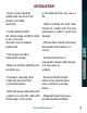
Please read the entire manual and follow the instructions and warnings carefully. Failure to do so can cause serious damage and/or injury, including loss of life. Be sure to obey all applicable local traffic and motor vehicle regulations as it pertains to this product. Improper installation will void manufacturer’s warranty. SAFETY INFORMATION USAGE: 4 • The Rear View Camera System is designed to help the driver safely detect people and/or objects helping to avoid damage or injury.
INSTALLATION: • Electric shock or product malfunction may occur if this product is installed incorrectly. or disconnected wire may cause a fire. • If smoke or a burning smell is detected, disconnect the system immediately. • Do not install the monitor where it may obstruct drivers view or obstruct an air bag device. SAFETY INFORMATION • While installing the Rear View System be careful with the wire positioning in order to avoid wire • Use this product within the voltage range specified. Failure damage.
If you have questions about this product, contact: Rear View Safety 1797 Atlantic Avenue Brooklyn, NY 11233 Tel: 1.800.764.1028 SAFETY INFORMATION IN NO EVENT SHALL SELLER OR MANUFACTURER BE LIABLE FOR ANY DIRECT OR CONSEQUENTIAL DAMAGES OF ANY NATURE, OR LOSSES OR EXPENSES RESULTING FROM ANY DEFECTIVE PRODUCT OR THE USE OF ANY PRODUCT.
Before drilling please check that no cable or wiring is on the other side of the wall. Please clamp all wires securely to reduce the possibility of them being damaged while vehicle is in use. Keep all cables away from hot or moving parts and electrical noisy components. We recommend doing a benchmark test before installation to insure that all components are working properly. Step 1: Choose the monitor and camera locations. BEFORE YOU BEGIN Step 2: Install all cables in vehicle, when necessary a 0.
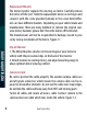
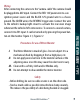
Replacement Monitor The mirror monitor replaces the existing car mirror. Carefully remove the mirror off the “pin”. Slide the replacement mirror on to the pin and secure it with the screw provided (already in the screw hole).Different cars have different brackets. Depending on your vehicle make and manufacturer. There are many methods to remove the original rearview mirror, however, please don’t force the mirror off the bracket.
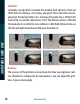
INSTALLATION GUIDE + TIPS Wiring After connecting the camera to the “camera cable” the camera should be plugged into AV2 input. Connect the RED 12V power wire to a an ignition power source and the BLACK 12V ground wire to a chassis ground. The GREEN wire is the REVERSE trigger wire. Connect this wire to the vehicle’s backup light circuit to activate the rear-view image whenever the vehicle shifts into reverse. To connect a second camera, connect it to AV1 input.
ADJUSTABLE GRID LINE Grid Lines Generally, to help drivers estimate the distance from obstacles, there are three lines for reference- red, yellow, and green. Those three lines are displayed on the monitor when car is reversing. The green line is 3M from the back of the car and the yellow line is 6.5 ft. The distant red line is 1M from the backside of car while the close red line is 0.4M. Both reference lines on the left and right should leave 0.2M space from the car.
FIGURE 1.1 INSTALLATION AND WIRE FIGURE 1.
HOW TO WIRE + SPLICING FIGURE 2.1 1. RED- Power (+) 2. YELLOW- Video 3. GREEN- Mirror / Normal Imaging 4. WHITE- Audio 5.
FIGURE 2.
GPS NAVIGATION MENU + FUNCTION MAIN MENU NAVIGATION FUNCTIONS AND FEATURES The GPS Navigation system uses a satellite signal to display your position on the navigation map. Set your destination, and the system will program the quickest, safest route. Enjoy your trip with navigation features that include realistic onscreen animations, as well as both voice and text indication.
VOLUME ADJUST In the setting menu, click the icon to enter the volume menu. Volume options include “speaker volume adjustment” and “screen tap sound”. Reverse With Confidence ™ GPS NAVIGATION MENU + FUNCTION 1. Map information: The navigation data may not be completely accurate because of changing real time road conditions and construction. Please check road status before your trip and always obey all traffic rules. 2.
GPS NAVIGATION MENU + FUNCTION NAVIGATION PATH In the setting menu, click the icon to enter navigation path menu. Use this menu to set a navigation path, or to change the auto start option on/off.
LANGUAGE SETTING In the setting menu, click the icon Twelve languages are available. to enter the language menu. Single click the button to enter GPS menu. In this menu you can reset the GPS, or check GPS information.
SYSTEM INFORMATION GPS NAVIGATION MENU + FUNCTION Single click the button to access the system information menu. DEFAULT SET Single click to enter the default settings menu. In this menu you can restore your system to default settings.
SCREEN CALIBRATION Single click the button to enter the screen calibration menu. GPS NAVIGATION MENU + FUNCTION Click “ok” to start the screen calibration. Follow the instructions, pressing the screen until the calibration succeeds. Click anywhere on the screen to save the calibration and exit to the main interface. If you do not want to save the calibration, wait 30 seconds to automatically exit to the main interface. When calibrating the screen, use your index finger to click the “+” on the screen.
GPS NAVIGATION MENU + FUNCTION ADJUST THE BRIGHTNESS OF MONITOR SCREEN AT NIGHT At night, the monitor brightness adjusts automatically, depending on driving conditions. If this is too bright or too dark for the driver, the brightness can be changed manually with the remote control. Choose “MENU”, then scroll “SEL/ REC” to choose “NIGHT BRIGHTNESS”, and adjust the brightness of the screen with “UP/DOWN.” SD/MMC CARD The included SD/MMC card contains navigation software, the map date and media files.
Note: Avoid storing the card high in temperatures, humidities, or in direct sunlight. Keep the card away from all liquid and corrosive material. This chapter will explain how to connect a cell phone to your system with Bluetooth. OPERATION METHOD Single click the button in main menu to open the Bluetooth menu as shown below.
BLUETOOTH SETTING + INSTRUCTIONS Play music with Bluetooth through your radio Single click 22 button to open the pair/connect menu as shown below.
Reverse With Confidence ™ BLUETOOTH SETTING + INSTRUCTIONS Search for Bluetooth devices 23
BLUETOOTH SETTING + INSTRUCTIONS Single click the Single click the pin and choose 24 button to modify the name of the device. button to enter the modify PIN menu. Choose your new when you are finished.
Single click the “Pairing history” button to display the pairing history. Reverse With Confidence ™ BLUETOOTH SETTING + INSTRUCTIONS Single click the “Search” button to search for Bluetooth devices.
BLUETOOTH SETTING + INSTRUCTIONS Select your phone, click “Connect”, and input your PIN to connect Bluetooth. The menu shown below will appear if the connection was successful. Notice that icons are now in color and selectable.
Single click the button to open the dial pad.
BLUETOOTH SETTING + INSTRUCTIONS Single click the button to make a call. Use the numbers to dial. When you receive a call, it will display “Calls” and show the phone number.
Single click “HANG UP” to refuse the call or click “ANSWER” to answer. Single click the button to open the phonebook. Reverse With Confidence ™ BLUETOOTH SETTING + INSTRUCTIONS When you answer a call, you will be able to hear the other person through the GPS navigator, and talk with them through the GPS navigator microphone. Single click the button to switch between the GPS navigator and your phone.
BLUETOOTH SETTING + INSTRUCTIONS Single click the Single click the 30 button to open the call history. button to open the A2DP. Use this menu to play music.
BLUETOOTH SETTING + INSTRUCTIONS 31 Reverse With Confidence ™
About Our Monitor 10.25” MONITOR SPECIFICATIONS 3” SPECIFICATIONS: 32 Screen Size: Display Screen: Display Resolution: Aspect Ratio: Color Depth: Pixel Pitch (mm) Power Consumption: Working Voltage: 4.3” TFT-LCD 400(H)x234(V) 16:9 16.7M dithering 0.219x0.
About Camera Reverse With Confidence ™ CAMERA SPECIFICATIONS SPECIFICATIONS: 33
CAMERA INSTALLATION Camera Installation Mounting Position view angle installation 34 position Rear View Safety 170º
No Image On Screen • Do a hard reset, unplug all cables and power cables, leave out for 1 minute and then re-connect them • Check to ensure that the connection to the camera is tight • Verify camera cable is plugged into port labeled Backup Camera • Verify cable is connected to monitor • Verify camera is connected to cable • Connect known working camera and cable to monitor • Verify Green trigger is receiving power Reverse With Confidence ™ TROUBLESHOOTING • Verify that the green positive trigger on pow
ONE YEAR WARRANTY REAR VIEW SAFETY, INC. WARRANTS THIS PRODUCT AGAINST MATERIAL DEFECTS FOR A PERIOD OF ONE YEAR FROM DATE OF PURCHASE. WE RESERVE THE RIGHT TO REPAIR OR REPLACE ANY SUCH DEFECTIVE UNIT AT OUR SOLE DISCRETION. REAR VIEW SAFETY, INC. IS NOT RESPONSIBLE FOR A DEFECT IN THE SYSTEM AS A RESULT OF MISUSE, IMPROPER INSTALLATION, DAMAGE OR MISHANDLING OF THE ELECTRONIC COMPONENTS. REAR VIEW SAFETY, INC. IS NOT RESPONSIBLE FOR CONSEQUENTIAL DAMAGES OF ANY KIND.
DISCLAIMER Reverse With Confidence ™ DISCLAIMER REAR VIEW SAFETY AND/OR ITS AFFILIATES DOES NOT GUARANTEE OR PROMISE THAT THE USER OF OUR SYSTEMS WILL NOT BE IN/PART OF AN ACCIDENT OR OTHERWISE NOT COLLIDE WITH AN OBJECT AND/OR PERSON. OUR SYSTEMS ARE NOT A SUBSTITUTE FOR CAREFUL AND CAUTIOUS DRIVING OR FOR THE CONSISTENT ADHERENCE TO ALL APPLICABLE TRAFFIC LAWS AND MOTOR VEHICLE SAFETY REGULATIONS.
A Safe Fleet Brand If you have any questions about this product, contact: Rear View Safety, Inc. 1797 Atlantic Avenue Brooklyn, NY 11233 800.764.1028 Better Cameras. Better Service. IT’S OUR GUARANTEE.