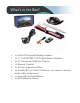
What’s in the Box? • • • • • • 1 x Color Waterproof Backup Camera 1 x 7" COLOR TFT LCD Digital Mirror Monitor 1 x 33’ Extension Cable for Camera 1 x Remote Control 1 x Power Connection Wire 1 x Double RCA + Power Converter (to connect external audio, video and power) • 1 x Screw Kit for Installation • 1 x 3M Adhesive Mount
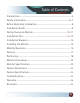
Table of Contents Introduction ...................................................................................................4 Safety Information ..................................................................................5-7 Before Beginning Installation...................................................................8 Installation Guide.........................................................................................9 Wiring Camera & Monitor..........................................
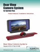
Introduction Please read all of the installation instructions carefully before installing the product. Improper installation will void manufacturer’s warranty. Congratulations on purchasing a Rear View Backup Camera System! With this manual you will be able to properly install and operate the unit. The Backup Camera System is intended to be installed as a supplement aid to your standard rear view mirror that already ex- ists in your vehicle.
Safety Information Please read the entire manual and follow the instructions and warnings carefully. Failure to do so can cause serious damage and/or injury, including loss of life. Be sure to obey all applicable local traffic and motor vehicle regulations as it pertains to this product. Improper installation will void manufacturer’s warranty. USAGE • The Rear View Camera System is designed to help the driver safely detect people and/or objects helping to avoid damage or injury.
Safety Information INSTALLATION • Electric shock or product malfunction may occur if this product is installed incorrectly. • Use this product within the voltage range specified. Failure to do so can cause electronic shock or product malfunction. • Take special care when cleaning the monitor. • Make sure to firmly affix the product before use. • If smoke or a burning smell is detected, disconnect the system immediately.
Safety Information If you have questions about this product, contact: Customer Service: Rear View Safety 1797 Atlantic Avenue Brooklyn, NY 11233 Tel: 1.800.764.1028 IN NO EVENT SHALL SELLER OR MANUFACTURER BE LIABLE FOR ANY DIRECT OR CONSEQUENTIAL DAMAGES OF ANY NATURE, OR LOSSES OR EXPENSES RESULTING FROM ANY DEFECTIVE PRODUCT OR THE USE OF ANY PRODUCT.
Before You Begin Installation Before drilling please check that no cable or wiring is on the other side of the wall. Please clamp all wires securely to reduce the possibility of them being damaged while vehicle is in use. Keep all cables away from hot or moving parts and electrical noisy components. We recommend doing a benchmark test before installation to insure that all components are working properly. Step 1: Choose the monitor and camera locations.
Installation Guide Camera 1. Attach camera bracket close to rear marker lights, centered on vehicle. 2. Attach camera to bracket using screws provided and adjust the angle. Cable 1. Be sure to position the cable properly. The aviation camera cable uses aircraft grade connectors which means the camera cable can be exposed to all weather elements, do not run the cable over sharp edges, do not kink the cable and keep away from HOT and rotating parts. 2. Fasten all cable and secure all excess cable.
Wiring Camera & Monitor • When installing a ONE (1) camera setup, connect camera extension cable from the rear view camera to port labeled “backup” (most systems port #3) Connect red 12V+ wire to ignition power source and black wire 12V- to chassis ground. Do not use white and yellow wires. • The blue wire is the REVERSE trigger wire. In typical rear-view installations, connecting this wire to the vehicle’s backup light circuit will activate the rear-view image whenever the vehicle shifts into reverse.
Wiring Camera & Monitor • When installing a TWO (2) camera setup, use ports #3 and #2 and use positive triggers Blue and White. • There is a built-in voltage regulator for our systems which can handle 12-24 volts. consumption is 10 to 30 Volts. F To automatically have camera and monitor turn ON when vehicle activates, simply twist BLUE positive trigger 12V+ to Red Power line 12V+ and wire to ignition power which can be an accessory switch/fuse line and black wire 12V- to chassis ground.
Installation Tips Sprinter Chassis third brake light camera Rear View Safety Pro Tips for Sprinter Chassis third brake light camera installation: 1. Always use our supplied camera cable from the rear to the monitor 2. You will find clean power hook-ups under the driver seat area to power our RVS monitor offerings. Determine positive and negative hook-ups are correct 3. There are two approved locations to pick up the reverse wire.
Installation Tips 5. Depending on your monitor choice; clip on 7 inch rear mirror monitor, 7 inch windshield button mount “windshield button provided” or our std 7 inch stand alone monitor, mount the monitor and then install the multiplex box either under the driver seat or above behind the driver seat on the wall ceiling area 6. If you are using a dbl din dash mount monitor, determine what impedance that monitor has. Std is 7 5, but a few monitors have a 70 impedance.
Installation Diagram Figure 1.1 Figure 1.2 Figure 1.
Installing the Monitor Monitor 33ft Extension Cable Optional Camera Available Video Out 1. DC12V-24V (red) 2. Ground (black) 3. Port #3 (blue) 4. Port #2 (white) 5.
Monitor Operation UP MENU DOWN V1/V2 ON/OFF • • • • • • • • • Brightness, Contrast, Saturation, Sharpness: Adjust image properties Picture Adjust: Stretch image horizontally (right/left and left/right) Turn: Toggle between mirror/normal image on each individual channel Name: Change name of teach individual channel Trigger Delay: Adjust time delay on each trigger Trigger Source: Toggle channel destination for each trigger Distance Grid: Toggle which channel distance grid lines will display on Grid Position
Splicing 1. 2. 3. 4. 5. 1. Red - Power (+) 2. Yellow - Video 3. Green - Mirror / Normal Imaging 4. White - Audio 5.
Positioning 18 REAR VIEW SAFETY
Monitor Dimensions Note: Monitor connection will vary depending on item configuration.
Monitor Specifications TFT LCD Digital Monitor Screen Size Digital 7” Display Format 16:9 Dot Resolution Display Brightness 800H x 3 (RGB) x 480V 400cd/m2 Viewing Angle 90° min Video Source 1Vp-p, 75Ω Video Input Power Supply 3 channel DC 12V-24V (+/-10%) Power Consumption 5W Video System Auto NTSC/PAL Weight 400G Dot Pitch 0.192H x 0.1805V Operating Temperature Overall Dimensions Impact Rating Sync System Reverse With Confidence™ -10°C - +65° C 9.5”L x 4.
Camera Dimensions 21 REAR VIEW SAFETY
Camera Camera Specifications 1/3 1099 Color Effective Pixels Array 976 (H) x 496 (V) Resolution 700 TVL View Angle 150° Lens Optical Format 2.21 mm Gamma Correction R = 0.45 - 1.0 Video System 1/4 inch Internal Night Vision Yes Power Source DC 12V (+/-10%) Electronic Iris 1/50, 160-1/100,000sec Usable Illumination S/N Ratio Video Output IR Switch Control 0.1 Lux > 48dB 1Vp.
Troubleshooting Monitor Displays Blue Screen & Displays No Signal • Do a hard reset, unplug all cables and power cables, then re-connect them. • Check to ensure that the connection to the camera is tight. • Verify camera cable is plugged into port labeled Backup Camera • Verify that the blue positive trigger on power harness is put to power 12v+. If the problem still persists, verify that alternate ports work.
Warranty One Year Warranty Rear View Safety Inc. warrants this product against material defects for a period of one year from date of purchase. We reserve the right to repair or replace any such defective unit at our sole discretion. Rear View Safety Inc. is not responsible for a defect in the system as a result of misuse, improper installation, damage or mis-handling of the electronic components. Rear View Safety Inc. is not responsible for consequential damages of any kind.
Disclaimer Rear View Safety and/or its affiliates does not guarantee or promise that the user of our systems will not be in/part of an accident or otherwise not collide with an object and/or person. Our systems are not a substitute for careful and cautious driving or for the consistent adherence to all applicable traffic laws and motor vehicle safety regulations. The Rear View Safety products are not a substitute for rearview mirrors or for any other motor vehicle equipment mandated by law.
Take Notes ________________________________________ ________________________________________ ________________________________________ ________________________________________ ________________________________________ ________________________________________ ________________________________________ ________________________________________ ________________________________________ ________________________________________ ________________________________________ ________________________________________ ________
If you have any questions about this product, contact: Rear View Safety, Inc. 1797 Atlantic Avenue Brooklyn, NY 11233 800.764.1028 BETTER CAMERAS. BETTER SERVICE. IT’S OUR GUARANTEE.