OPERATOR’S MANUAL PC30 PRUNER/TRIMMER RY52001 / RY52001A Your pruner/trimmer has been engineered and manufactured to Ryobi’s high standard for dependability, ease of operation, and operator safety. When properly cared for, it will give you years of rugged, trouble-free performance. WARNING: To reduce the risk of injury, the user must read and understand the operator’s manual before using this product. Thank you for buying a Ryobi product.
TABLE OF CONTENTS n Introduction ..................................................................................................................................................................... 2 �n General Safety Rules ....................................................................................................................................................... 3 �n Specific Safety Rules.............................................................................................................
GENERAL SAFETY RULES �n Always stop the engine and remove the spark plug wire before making any adjustments or repairs except for carburetor adjustments. WARNING! Read and understand all instructions. Failure to follow all instructions listed below, may result in electric shock, fire and/or serious personal injury. �n Inspect the unit before each use for loose fasteners, fuel leaks, etc. Replace any damaged parts before use. �n The chain may rotate during carburetor adjustments.
SPECIFIC SAFETY RULES SPECIFIC SAFETY RULES FOR PRUNER USE n To prevent electrical shock or serious personal injury, do not use this product with any AC power head. n Kickback is a dangerous reaction that can lead to serious injury. Kickback may occur when the moving chain contacts an object at the upper portion of the tip of the guide bar or when the wood closes in and pinches the chain in the cut.
SYMBOLS Some of the following symbols may be used on this tool. Please study them and learn their meaning. Proper interpretation of these symbols will allow you to operate the tool better and safer. SYMBOL NAME DESIGNATION/EXPLANATION Safety Alert Precautions that involve your safety. Read The Operator’s Manual To reduce the risk of injury, user must read and understand operator’s manual before using this product.
SYMBOLS The following signal words and meanings are intended to explain the levels of risk associated with this product. SYMBOL SIGNAL MEANING DANGER: Indicates an imminently hazardous situation, which, if not avoided, will result in death or serious injury. WARNING: Indicates a potentially hazardous situation, which, if not avoided, could result in death or serious injury. CAUTION: Indicates a potentially hazardous situation, which, if not avoided, may result in minor or moderate injury.
FEATURES PRODUCT SPECIFICATIONS Engine displacement ....................................................................................................................................................... 30cc Bar length ....................................................................................................................................................................... 10 in. String cutting width ................................................................................................
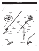
FEATURES KNOW YOUR PRUNER/TRIMMER PRIMER BULB See Figure 1. Before attempting to use this product, familiarize yourself with all operating features and safety rules. The priming bulb pumps fuel from the fuel tank to the carburetor. This is necessary only when starting a cold engine or after refueling an engine that has run out of fuel. CHOKE LEVER SHOULDER STRAP The choke lever opens and closes the choke valve in the carburetor. Positions available include FULL CHOKE (A), HALF CHOKE (B), and RUN (C).
ASSEMBLY n Pull apart the ends of the bracket to expand slightly. WARNING: n Slide the bracket over the power head shaft immediately behind the “J” Barrier Handle. To prevent accidental starting that could cause serious personal injury, always disconnect the engine spark plug wire from the spark plug when assembling parts. n Squeeze bracket ends together to retighten. n Reinstall the bolt, lock washer, and hex nut to secure. n Connect the latch on the shoulder harness to the strap hanger.
ASSEMBLY To remove: n Loosen the knob. n Carefully pour fuel into the tank. Avoid spillage. n Prior to replacing the fuel cap, clean and inspect the gasket. n Push in the button and twist the shafts to remove and separate ends. COUPLER GUIDE RECESS n Immediately replace fuel cap and hand tighten. Wipe up any fuel spillage. NOTE: It is normal for smoke to be emitted from a new engine after first use. POWER HEAD SHAFT WARNING: Always shut off engine before fueling.
OPERATION n Make a shallow first cut (1/4 of limb diameter) on the underside of the limb close to the main limb or trunk. WARNING: n Make a second cut from the top side of the limb outboard from the first cut. Do not allow familiarity with tools to make you careless. Remember that a careless fraction of a second is sufficient to inflict serious injury. n Make a final cut close to trunk. N � OTE: For second and final cuts (from top of limb or branch), hold front cutting guide against the limb being cut.
OPERATION LIMBING AND PRUNING See Figures 8 - 9. This unit is designed for trimming small branches and limbs up to 6 in. in diameter. For best results, observe the following precautions. n Plan the cut carefully. Be aware of the direction in which the branch will fall. n Branches may fall in unexpected directions. Do not stand directly under the branch being cut. n The most typical cutting application is to position the unit at an angle of 60° or less, depending on the specific situation, as shown below.
OPERATION GRASS DEFLECTOR LINE TRIMMING CUT-OFF BLADE Always operate trimmer at full throttle. Cut tall grass from the top down. This will prevent grass from wrapping around the shaft housing and string head which could cause damage from overheating. If grass becomes wrapped around the string head, STOP THE ENGINE, disconnect the spark plug wire, and remove the grass. Prolonged cutting at partial throttle will result in oil dripping from the muffler. See Figure 12.
OPERATION POSITION FOR STARTING See Figure 13. Lay the pruner on the ground and ensure that no objects or obstructions are in the immediate vicinity. Make sure nothing can come in contact with the bar and chain. ENGINE SWITCH THROTTLE TRIGGER Fig. 13 STARTING AND STOPPING Fig. 14 PRIMER BULB See Figures 14 - 16. Unit should be on a flat, bare surface for starting. n Slowly push the primer bulb 5 times. STARTER GRIP n Set the choke lever to the FULL CHOKE position (A).
MAINTENANCE n Stop the engine before setting the chain tension. Make sure the guide bar nut is loose to finger tight, turn the chain tensioning screw clockwise to tension the chain. Refer to “Replacing the Bar and Chain” for additional information. WARNING: When servicing, use only identical Ryobi replacement parts. Use of any other parts may create a hazard or cause product damage.
MAINTENANCE REPLACING THE BAR n Remove all slack from chain by turning the chain tensioning screw clockwise, assuring that the chain seats into the bar groove during tensioning. See Figures 19 - 24. n Lift the tip of the bar up to check for sag. Release the tip of the bar, and turn the chain tensioning screw 1/2 turn clockwise. Repeat this process until sag does not exist. WARNING: To avoid possible serious injury, stop engine before replacing the bar, chain, or performing any maintenance operation.
MAINTENANCE IDLE SPEED ADJUSTMENT CHAIN OILER See Figure 25. If the chain turns at idle, the idle speed screw needs adjusting on your trimmer engine. Turn the idle speed screw counterclockwise to reduce the idle RPM and stop the chain movement. If the saw chain still moves at idle speed, contact a service dealer for adjustment and discontinue use until the repair is made. See Figure 26. n Use Premium Bar and Chain Oil.
MAINTENANCE CHAIN MAINTENANCE n Use a 5/32 in. diameter round file and holder. See Figure 27. For smooth and fast cutting, the chain needs to be maintained properly. The following conditions indicate that the chain requires sharpening: n Wood chips are small and powdery n Keep the file level with the top plate of the tooth. Do not let the file dip or rock.
MAINTENANCE CAUTION: Dull or improperly sharpened chain can cause excessive engine speed during cutting which may result in severe engine damage. SPOOL RETAINER WARNING: Improper chain sharpening increases the potential of kickback. Failure to replace or repair damaged chain can cause serious injury. Fig. 32 SPRING SPOOL REPLACEMENT SLOTS NEW PREWOUND SPOOL See Figures 32 - 33. If replacing string only, refer to “String Replacement” later in this manual. Use only monofilament string.
MAINTENANCE STRING REPLACEMENT See Figures 34 - 36. Use only monofilament string. Use original manufacturer’s replacement string for best performance. n Stop the engine, disconnect the spark plug wire. Hold the string head and unscrew the spool retainer. To remove the spool retainer: n Turn the spool retainer counterclockwise. n Remove the spool from the string head. NOTE: Keep the spring attached to the spool. Remove any old string remaining on the spool.
MAINTENANCE CLEANING THE EXHAUST PORT AND MUFFLER LATCH Depending on the type of fuel used, the type and amount of oil used, and/or your operating conditions, the exhaust port and muffler may become blocked with carbon deposits. If you notice a power loss with your gas powered tool, a qualified service technician will need to remove these deposits to restore performance.
TROUBLESHOOTING PROBLEM CAUSE REMEDY Engine will not start. No spark. Check spark. Remove spark plug. Reattach the spark plug cap and lay spark plug on metal cylinder. Pull the starter rope and watch for spark at spark plug tip. If there is no spark, repeat test with a new spark plug. No fuel. Push primer bulb until bulb is full of fuel. If bulb does not fill, primary fuel delivery system is blocked. Contact a servicing dealer. If primer bulb fills, engine may be flooded, proceed to next item.
WARRANTY LIMITED WARRANTY STATEMENT Ryobi Technologies, Inc. warrants to the original retail purchaser that this Ryobi Technologies, Inc. product is free from defect in material and workmanship and agrees to repair or replace, at Ryobi Technologies, Inc.’s discretion, any defective product free of charge within these time periods from the date of purchase.
WARRANTY THE FOLLOWING CALIFORNIA AIR RESOURCES BOARD (CARB) STATEMENT ONLY APPLIES TO MODEL NUMBERS REQUIRED TO MEET THE CARB REQUIREMENTS. RYOBI TECHNOLOGIES INC. LIMITED WARRANTY FEDERAL AND CALIFORNIA EMISSION CONTROL SYSTEMS NON-ROAD AND SMALL OFF-ROAD ENGINES The U.S. Environmental Protection Agency (EPA), the California Air Resources Board (CARB), and Ryobi Technologies Inc. are pleased to explain the Emission Control System Warranty on your non-road or small off-road engine.
WARRANTY THIS PRODUCT WAS MANUFACTURED WITH A CATALYST MUFFLER (RY52001A ONLY) Congratulations! You have made an investment toward protecting the environment. In order to maintain this product’s original emission level, please refer to the maintenance section below.
OPERATOR’S MANUAL PC30 PRUNER/TRIMMER RY52001 / RY52001A WARNING: The engine exhaust from this product contains chemicals known to the State of California to cause cancer, birth defects or other reproductive harm. CALIFORNIA PROPOSITION 65 • SERVICE Now that you have purchased your tool, should a need ever exist for repair parts or service, simply contact your nearest Ryobi Authorized Service Center. Be sure to provide all pertinent facts when you call or visit.