MODEL 2075r GAS TRIMMER OPERATOR’S MANUAL FOR QUESTIONS, CALL 1-800-345-8746 in U.S.
INTRODUCTION THANK YOU Thank you for purchasing this quality product. This modern outdoor power tool is designed to provide many hours of useful service. You will find it to be a great labor-saving device. This operator’s manual provides you with easy-tounderstand operating instructions. Read the entire manual and follow all of the instructions to keep your new outdoor power tool in top operating condition.
SPARK ARRESTOR NOTE: For users on U.S. Forest Land and in the states of California, Maine, Oregon and Washington. All U.S. Forest Land and the state of California (Public Resources Codes 4442 and 4443), Oregon and Washington require, by law that certain internal combustion engines operated on forest brush and/or grasscovered areas be equipped with a spark arrestor, maintained in effective working order, or the engine be constructed, equipped and maintained for the prevention of fire.
SAFETY WARNINGS • IMPORTANT SAFETY INFORMATION • READ ALL INSTRUCTIONS BEFORE OPERATING • Read the instructions carefully. Be familiar with the controls and proper use of the unit. • Children and adolescents must not manipulate units, except for adolescents in training and under the supervision of a specialist. • All guards and safety attachments must be installed properly before operating the unit. • Thoroughly inspect the unit for loose or damaged parts before each use.
SAFETY WARNINGS • Keep all bystanders, especially children and pets, at least 30 feet (9.1 m) away from the unit during operation. • Do not operate the engine faster than the speed necessary to cut, trim or edge. Do not run the engine at high speed when not cutting. • Always stop the engine when cutting is delayed or when walking from one cutting location to another. • Do not operate unit without both trimming lines extended, and the proper line installed.
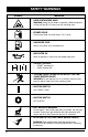
SAFETY WARNINGS SYMBOL MEANING • KEEP BYSTANDERS AWAY WARNING: Keep all bystanders, especially children and pets, at least 30 feet (9.1 m) away from the trimming area. • PRIMER BULB Push primer bulb, fully and slowly, 5 to 7 times. • UNLEADED FUEL Always use clean, fresh unleaded fuel. • INDICATES OIL Refer to operator's manual for the proper type of oil. • CHOKE CONTROL • • “START” position (A). “RUN” position (B).
ASSEMBLY INSTRUCTIONS INSTALLING AND ADJUSTING THE LOOP HANDLE If the loop handle is not assembled on this model, use the following instructions: 1. Place the loop handle and bottom handle clamp on the boom shaft (Fig. 1). 2. Install, one at a time, the four (4) screws and four (4) hex nuts with a Phillips screwdriver. NOTE: Install all four (4) screws before you tighten any of them. 3. Adjust the loop handle to the desired position. Guard Mount Fig. 2 4. Tighten the clamp screws securely.
OIL AND FUEL INFORMATION Old or improperly mixed fuel are usually the main reasons for the unit not running properly. Be sure to use fresh, clean fuel and follow the instructions carefully for the proper fuel/oil mixture. NOTE: Alcohol-blended fuel absorbs moisture (water). As little as 1% moisture in the fuel can cause fuel and oil to separate and form acids when stored. If this type of fuel must be used, use fresh fuel (less than 60 days old), and mix according to the mixing instructions.
OPERATING INSTRUCTIONS STARTING/STOPPING 10.To stop the engine, put the IGNITION SWITCH IN THE "OFF" POSITION (Fig. 5). WARNING: Operate this unit only in a well-ventilated area outdoors. Carbon monoxide exhaust fumes can be lethal in a confined area. WARNING: Avoid accidental starting. Be in the starting position whenever pulling the starting rope. To avoid serious personal injury, the operator and unit must be in a stable position while starting. Ignition Switch 1.
OPERATING INSTRUCTIONS OPERATING THE CLICK-LINK SYSTEM This unit is equipped with a Click-Link® System, which enables optional attachments to be installed on the unit. The optional attachments are: Blower/Vacuum. . . . . . . . . . . . . . . . . . . . . BV720r Cultivator . . . . . . . . . . . . . . . . . . . . . . . . . GC720r Edger . . . . . . . . . . . . . . . . . . . . . . . . . . . . LE720r Hedgetrimmer . . . . . . . . . . . . . . . . . . . . . HS720r Snowthrower. . . . . . . . . . . . . . . . . . . . .
OPERATING INSTRUCTIONS ADJUSTING TRIMMING LINE LENGTH DECORATIVE TRIMMING Your unit is equipped with a cutting head that allows the operator to release more trimming line without stopping the engine. To release additional line, lightly tap the cutting head on the ground (Fig. 11) while operating the unit at high speed. Decorative trimming is accomplished by removing all vegetation around trees, posts, fences, etc. Rotate the entire unit so that the cutting head is at a 30° angle to the ground (Fig. 12).
MAINTENANCE AND REPAIR INSTRUCTIONS LINE INSTALLATION FOR THE SPEEDSPOOL® The trimming line in the speed spool may be replaced by two different methods. • Winding the existing inner reel with new line • Installing a prewound inner reel TO INSTALL NEW TRIMMING LINE, IT IS NOT NECESSARY TO REMOVE THE BUMP KNOB. 2. Insert 10 feet (2.5 m) of .080 in (2.03 mm) trimming line into one of the two eyelets and push it up through the line loading hole in the inner reel (Fig. 14).
MAINTENANCE AND REPAIR INSTRUCTIONS 5. Repeat the procedure with the second eyelet and use the same amount of line as specified in Step 2. 6. Wind the inner reel counterclockwise until approximately four (4) inches of line remains outside of the eyelets in the outer spool (Fig. 17). 1. If you need to remove the Bump Knob to clean the spool or remove jammed, excess line, hold the outer spool, and unscrew the Bump Knob counterclockwise (Fig. 19).
MAINTENANCE AND REPAIR INSTRUCTIONS NOTE: The inner reel must be completely dry before reinstalling it into the outer spool. Do not lubricate the inner reel or outer spool assembly. 4. Clean the shaft and the inner surface of the outer spool. To clean the shaft underneath the plunger, press down on the plunger (Fig. 22). Remove any dirt and/or debris from the shaft. Shaft AIR FILTER MAINTENANCE CLEAN AND RE-OIL THE AIR FILTER EVERY 10 HOURS OF OPERATION.
MAINTENANCE AND REPAIR INSTRUCTIONS 4. Apply enough clean motor oil to lightly coat the filter (Fig. 27). Fig. 27 The condition of the air filter is important to the operation of the unit. A dirty air filter will restrict the air flow, which upsets the fuel-air mixture in the carburetor. The resulting symptoms are often mistaken for an out-of-adjustment carburetor. Therefore, check the condition of the air filter before adjusting the carburetor. Refer to Air Filter Maintenance.
MAINTENANCE AND REPAIR INSTRUCTIONS REPLACING THE SPARK PLUG STORAGE Use a Champion RCJ-6Y spark plug (or equivalent). Correct air gap is 0.025 in. (0.655 mm). Remove plug after every 50 hours of operation and check its condition. 1. Stop the engine and allow it to cool. Pull the wire off of the spark plug. If the unit will be stored for an extended period of time, use the following storage procedure. 1. Drain all fuel from the fuel tank and drain into a container with the same 2-cycle fuel mixture.
TROUBLESHOOTING PROBLEM Engine will not start CAUSE Ignition switch is “OFF” Empty fuel tank Primer bulb wasn't pressed enough Engine flooded Old or Improperly Mixed Fuel ACTION Turn switch to “ON” Fill fuel tank Press primer bulb fully and slowly 5-7 times Use starting procedure WITHOUT USING CHOKE Drain fuel tank / Add fresh fuel mixture Fouled spark plug Excessive oil in oil/fuel mixture or Old Fuel Replace spark plug / Drain fuel tank / Add fresh fuel mixture Engine will not idle Carburetor misad
SPECIFICATIONS ENGINE Engine Type . . . . . . . . . . . . . . . . . . . . . . . . . . . . . . . . . . . . . . . . . . . . . . . . . Air-Cooled, 2-Cycle Displacement . . . . . . . . . . . . . . . . . . . . . . . . . . . . . . . . . . . . . . . . . . . . . . . . 1.4 cu. in. (22.5 cc) Clutch Type . . . . . . . . . . . . . . . . . . . . . . . . . . . . . . . . . . . . . . . . . . . . . . . . . . . . . . . . Centrifugal Operating RPM . . . . . . . . . . . . . . . . . . . . . . . . . . . . . . . . . . . . . . . .
CALIFORNIA EMISSION CONTROL WARRANTY STATEMENT YOUR WARRANTY RIGHTS AND OBLIGATIONS The California Air Resources Board and Ryobi Outdoor Products (ROP), is pleased to explain the emission control system warranty on your 1995 and later lawn and garden equipment engine. In California, new lawn and garden equipment engines must be designed, built and equipped to meet the State's stringent anti-smog standards.
LIMITED TWO-YEAR WARRANTY RYOBI OUTDOOR PRODUCTS warrants each new RYOBI Product for two (2) years according to the following terms. This warranty extends to the original retail purchaser only and commences on the date of original retail purchase. Any part of the RYOBI Product manufactured or supplied by RYOBI and found in the reasonable judgement of RYOBI to be defective in material or workmanship will be repaired or replaced by an authorized RYOBI service dealer without charge for parts and labor.