227L/LD 232L 240L Operator's manual Read through the Operator‘s manual carefully and understand the content before using the machine.
SYMBOL EXPLANATION Symbols WARNING! Clearing saws, brushcutters and trimmers can be dangerous! Careless or incorrect use can result in serious or fatal injury to the operator or others. Read through the Operator‘s Manual carefully and understand the content before using the machine. Always use • A protective helmet where there is a risk of falling objects • Ear protection • Approved eye protection max 10000 rpm • Beware of thrown objects and ricochets. 15 m 50FT • Use anti-slip and stable boots.
CONTENTS Husqvarna AB has a policy of continuous product development and therefore reserves the right to modify the design and appearance of products without prior notice. ! WARNING! Under no circumstances may the design of the machine be modified without the permission of the manufacturer. Always use genuine accessories. Non-authorised modifications and/or accessories can result in serious personal injury or the death of the operator or others. List of contents SYMBOL EXPLANATION Symbols ...............
SAFETY INSTRUCTIONS Personal protective equipment MPORTANT INFORMATION • A clearing saw, brushcutter or trimmer used incorrectly or carelessly can become a dangerous tool, that can cause serious or fatal injury to the operator or others. It is extremely important that you read and understand the content of this manual. • When using a trimmer, personal protective equipment approved by the appropriate authorities must be used.
SAFETY INSTRUCTIONS 4. Vibration damping system Your machine is equipped with a vibration damping system, which is designed to give as vibration-free and comfortable use as possible. Use of incorrectly wound cord or incorrect cutting equipment increases the level of vibration. The machine’s vibration damping system reduces the transfer of vibrations between the engine unit/ cutting equipment and the machine’s handle unit. 5.
SAFETY INSTRUCTIONS Control, maintenance and service of the machine‘s safety equipment IMPORTANT INFORMATION • All service and repairs to the machine require special training. • This applies especially to the machine‘s safety equipment. If the machine does not meet any of the controls listed below you should contact your service workshop. • The purchase of one of our products guarantees that professional repair and servicing will be carried out on it.
SAFETY INSTRUCTIONS 6. Cutting equipment Cutting equipment The section describes how through correct maintenance and through using the right type of cutting equipment you can: • Obtain maximum clearing capacity. • Increase the service life of the cutting equipment. Two basic rules: 1)Only use the cutting and guard equipment we recommend! See chapter “Technical data“. 2)Check the cutting equipment with regard to damage and crack formation. Damaged cutting equipment should always be replaced. 7.
SAFETY INSTRUCTIONS General safety instructions IMPORTANT INFORMATION • The machine is only designed for trimming grass. • The only accessories to be used with the engine unit as a drive source are the cutting units we recommend in the chapter “Technical data“. • Never use the machine if you are tired, if you have consumed alcohol, or if you are taking medicines that can affect your sight, your judgement or the control of your body. • Use personal protective equipment.
SAFETY INSTRUCTIONS General working instructions IMPORTANT INFORMATION • This section takes up the basic safety precautions for working with the trimmer. • If you encounter a situation where you are uncertain how to proceed you should ask an expert. Contact your dealer or your service workshop. • Avoid all usage which you consider to be beyond your capability. Basic working techniques • Always drop to idling speed after each working operation.
SAFETY INSTRUCTIONS Clearing • The clearing technique removes all unwanted vegetation. Keep the trimmer head just above the ground and tilt it. Let the end of the cord strike the ground around trees, posts, statues and the like. NOTE! This technique increases the wear on the cord. Trimming • The trimmer is ideal to cut grass that is difficult to reach using a normal lawn mower. Keep the cord parallel to the ground when cutting.
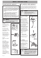
WHAT IS WHAT? What is what on the trimmer? 1. 2. 3. 4. 5. 6. 7. 8. 9. 10. 11. 12. 13. 14. Trimmer head Grease filler cap Angle gear Spray guard Shaft Loop handlebar Throttle Stop switch Throttle trigger lock Suspension for harness Cylinder cover Starter handle Fuel tank Choke 15. 16. 17. 18. 19. 20. 21. 22. 23. Air purge Air filter cover Clutch cover Handlebar adjustment Locking nut Support flange Drive disc Shaft coupling Socket spanner 24. 25. 26. 27.
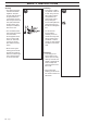
ASSEMBLY Assembling the loop handlebar • Unscrew the handle and plastic cover from the handlebar bracket. • Place the loop handlebar with the handlebar holder on the handlebar bracket. Fit the handle and plastic cover. Do not tighten too tight. • Put on the harness and hang the trimmer in the suspension hook. Now finely adjust so that the trimmer gives a comfortable working position when it‘s attached to the harness. Tighten the handle.
ASSEMBLY Assembling other guards and cutting equipment Assembling and dismantling the two-part shaft (227LD) • Fit the guard (A) intended for use with the trimmer head. Secure using four bolts (L) and the support plate (M) as shown in the diagram. Assembling: • Make sure the handle is loose. A L • Fit the disc drive (B) on the output axle. B C M • Guide the cut-out on the lower section of the shaft into the coupling‘s locking plate on the upper section of the shaft.
FUEL HANDLING Fuel mixture NOTE! The machine is fitted with a two-stroke engine and must always be run on a mixture of petrol and two-stroke oil. It is important to measure the quantity of oil accurately, to ensure the correct mixture ratio. Small discrepancies in the amount of oil have a great bearing on the proportions of the fuel mixture when mixing small amounts of fuel. ! WARNING! Always provide good ventilation when handling fuel.
START AND STOP Control before starting For reasons of safety follow these recommendations! • Check that the support flange is not cracked due to fatigue or due to being tightened too much. Discard the support flange if it is cracked. • Ensure the locking nut has not lost its captive force. The nut lock should have a locking force of at least 1.5 Nm. The tightening torque of the locking nut should be 35-50 Nm. • Check that the trimmer head and spray guard are not damaged or cracked.
MAINTENANCE Carburettor Basic setting Your Husqvarna product has been designed and manufactured to specifications that reduce harmful emissions. After your unit has been run 8-10 tanks of fuel the engine has broken in. To ensure that your unit is at peak performance and producing the least amount of harmful emissions after break in, have your authorized servicing dealer, who has a revolution counter at his disposal, to adjust your carburettor for optimum operating conditions.
MAINTENANCE Final setting of the idling speed T Correctly adjusted carburettor Adjust the idling speed with the screw T, if it is necessary to readjust. First turn the idle speed adjusting screw T clockwise until the cutting attachment starts to rotate/ move. Then turn, counterclockwise until the cutting attachment stops. A correctly adjusted idle speed setting occurs when the engine runs smoothly in every position.
MAINTENANCE Muffler Cooling system NOTE! Some mufflers are fitted with a catalytic converter. See “Technical data” to see whether your machine is fitted with a catalytic converter. To maintain as low operating temperature as possible the engine is equipped with a cooling system. The cooling system consists of: 1. An air intake on the starter unit. 2. Cooling fins on the flywheel. 3. Cooling fins on the cylinder 4. Cylinder cover (leads cold air onto the cylinder).
MAINTENANCE Air filter Two-part shaft The air filter should be cleaned regularly removing dust and dirt to avoid: • carburettor malfunction • starting problems • reduced engine power • unnecessary wear to engine parts • abnormal fuel consumption Clean the filter after every 25 hours or more regularly if operating conditions are exceptionally dusty. The end of the drive axle in the lower shaft should be lubricated with grease every 30 hours.
MAINTENANCE Weekly maintenance 1. Check the starter, the starter cord and the return spring. 2. Make sure that the vibration damping elements are not damaged. 3. Clean the outside of the spark plug. Remove and check the electrode gap. Adjust the gap to 0.5 mm or change the spark plug. 4. Clean the cooling fins on the flywheel. 5. Clean or replace the muffler’s spark arrest screen (not on mufflers with a catalytic converter). Monthly maintenance 1 1 1. Clean the fuel tank. 2 2.
TECHNICAL DATA Technical data 227L/LD 232L 240L Engine Cylinder capacity, cm3 Cylinder bore, mm Stroke length, mm Idling speed, rpm Recommended max. speed, rpm Speed of output axle, rpm Max. engine output, acc.
EU declaration of conformity (Only applies to Europe) (Directive 89/392/EEC, Annex II, A) We, Husqvarna AB, S-561 82 Huskvarna, Sweden, tel: +46 36-146500, declare under sole responsibility that the clearings saws Husqvarna 227L/LD, 232L/LD and 240L from 1998’s serial numbers and onwards (the year is clearly stated in plain text on the type plate with subsequent serial number), are in conformity with the following standards or other normative documents following the provisions in the COUNCIL’S DIRECTIVES: -
Super Auto II Super Auto II 1" 1 2 3 4 2,4 mm .
Tri Cut 1 B 3 >20mm 2 4 5 >20mm 6 8 24 – English 7 !
Trimmy H II 1 2 3 4 5 8 7 6 9 English – 25
Trimmy Hit 2 3 " 1 “Click” 7,0 m 23' 12 cm 5" 4 ~ 3,5 m 11' 5 6 7 9 8 “Click” " 10 11 15 cm 6" 26 – English
Trimmy Hit Junior 2 3 2,0-2,4 mm .080-.
Trimmy Hit Pro 2 3 2,0-2,4 mm .080-.
1 2 2,0-2,4 mm .080-.
1 3 5 2 4 8 30 – English 7 6 9 ´*30^¶6S¨
Trimmy SII ~ 15 cm 6' 1 2 3 N 4 ~ 15 cm 6' 502 26 04-01 502 25 56-01 502 25 53-01 729 53 27-71 (x3) 502 26 24-01 (x2) 738 21 03-04 740 43 14-00 502 26 03-01 502 25 52-01 502 26 01-01 735 31 19-00 502 27 07-01 502 26 86-01
´*30^¶6S¨ 2001W07
We hope you find the links below useful. For further gardening information visit www.GardenResources.co.