OPERATOR'S MANUAL ROUTER MOUNTING KIT 4950301 (FOR USE WITH BT3000 AND BT3100 TABLE SAWS) Your new router mounting kit has been engineered and manufactured to Ryobi's high standard for dependability, ease of operation, and operator safety. Properly cared for, it will give you years of rugged, trouble-free performance. WARNING: To reduce the risk of injury, the user must read and understand the operator’s manual. Thank you for buying a Ryobi router mounting kit.
TABLE OF CONTENTS ■ Rules for Safe Operation ............................................................................................................................................ 3-4 ■ Unpacking ...................................................................................................................................................................... 5 ■ Tools Needed .........................................................................................................................
RULES FOR SAFE OPERATION Safe operation of this accessory requires that you read and understand this operator's manual, the operator’s manual for the table saw and all labels affixed to the tool. READ ALL INSTRUCTIONS ■ KNOW YOUR ACCESSORY. Read the operator's manual carefully. Learn the product's applications and limitations as well as the specific potential hazards related to this product. ■ KEEP THE WORK AREA CLEAN. Cluttered work areas and work benches invite accidents.
RULES FOR SAFE OPERATION The purpose of safety symbols is to attract your attention to possible dangers. The safety symbols, and the explanations with them, deserve your careful attention and understanding. The safety warnings do not by themselves eliminate any danger. The instructions or warnings they give are not substitutes for proper accident prevention measures. SYMBOL MEANING SAFETY ALERT SYMBOL: Indicates danger, warning or caution. May be used in conjunction with other symbols or pictographs.
UNPACKING WARNING: WARNING: Unplug the power supply cord of your saw from the electrical outlet before you begin mounting this kit. It should remain disconnected until the mounting operation is complete, all attachments are installed properly, and they have been checked to make sure they are secure. Failure to unplug your saw could result in accidental starting causing possible serious personal injury.
LOOSE PARTS THROAT PLATES 5/16 in. WASHERS GUIDE FENCE BRACKET WITH GUIDE BLOCK 1/2 in. KNOB BOLTS ROUTER MOUNTING PLATE TABLE CLAMPING BRACKET 3/4 in. KNOB BOLT 5/16 in. T-NUTS POST M8 SCREWS 5/16 in. WASHER #10-32 SCREWS SPACER GUARD/DUST COVER WITH PIVOT ASSEMBLY #5/16-18 SCREWS #1/4-20 SCREWS Fig. 1 LIST OF LOOSE PARTS Your #4950301 Router Mounting Kit includes the following parts: DESCRIPTION DESCRIPTION QUANTITY Guide Fence Bracket with Guide Block ..................
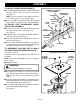
ASSEMBLY T-NUT SHOWN BETWEEN ADJUSTMENT SCREWS WARNING: The saw's motor cord must be disconnected from the receptacle on the saw when using this kit. The power cord of the router must be plugged into the receptacle on the saw. The saw's master switch must be used to turn the router ON and OFF. Failure to do so could result in serious injury. T-NUT REAR ADJUSTMENT SCREW IMPORTANT This router kit has been specifically designed for use with Ryobi Routers.
ASSEMBLY TO INSTALL GUIDE FENCE BRACKETS: GUARD/DUST COVER WITH PIVOT ASSEMBLY CARRIAGE BOLT (NOT SHOWN) KNOB NUT ■ To install the guide fence brackets, align each bracket with two of the T-nuts on top of the rip fence. See Figure 4. NOTE: Use the front two T-nuts and the back two T-nuts leaving the one in the middle empty. ■ Secure the guide fence brackets to the rip fence with 5/16 in. washers and the 5/16 in. x 1/2 in. knob bolts.
ASSEMBLY TO ASSEMBLE ROUTERS WITH 2-HOLE PATTERN TO ROUTER MOUNTING PLATE (cont'd): 2–HOLE ROUTER WITH MOUNTING PLATE ATTACHED See Figures 5 and 6. ■ Secure the router mounting plate to the router using two 5/16-18 x 3/4 in. bolts provided in the router mounting kit. Tighten screws securely. ■ Properly installed, the mounting plate will be securely attached to the router. See Figure 6. TO ASSEMBLE ROUTERS WITH 3-HOLE PATTERN TO ROUTER MOUNTING PLATE: See Figures 7 and 8.
ASSEMBLY TO ASSEMBLE ROUTERS WITH 4-HOLE PATTERN TO ROUTER MOUNTING PLATE: See Figures 9 and 10. For Ryobi routers, model numbers RE600 and RE601. ■ Unplug the router. WARNING: ROUTER WITH 4–HOLE PATTERN ROUTER MOUNTING SCREWS Unplug the router to avoid possible injury. ■ Make sure the router switch is OFF and the router is not connected to a power source. ROUTER BASE ROUTER MOUNTING PLATE ■ Place the router upside down on a workbench and remove the subbase screws and subbase from the router.
ROUTER MOUNTING TO MOUNT ROUTER WITH PLATE TO ACCESSORY TABLE: THROAT PLATE #1/4-20 SCREWS (PROVIDED) ■ Place the router with the mounting plate under the accessory table. See Figure 11. ACCESSORY TABLE ■ Secure the mounting plate to accessory table using the four #1/4-20 x 1/2 in. flat head screws provided. NOTE: The accessory table can be removed from the table saw to attach the router and mounting plate.
ROUTER MOUNTING around the raised portion on the underside of the accessory table, clamping it tightly against the rear rail. ■ Secure with a 5/16 in. washer and 5/16-18 x 3/4 in. knob bolt. ■ Tighten knob bolt securely. DIRECTION OF FEED IS FROM RIGHT TO LEFT AGAINST SHARP EDGES OF ROTATING BIT FINAL ASSEMBLY: After the router mounting parts have been assembled, your setup should be similar to Figure 13. ■ Compare your setup and make any necessary adjustments. ■ Recheck all knob bolts, attachments, etc.
NOTES Page 13
4950301 ROUTER MOUNTING KIT 5 3 4 6 5 8 7 10 9 3 4 11 2 1 3 12 13 21 15 20 4 14 24 22 19 23 16 17 18 Page 14
4950301 ROUTER MOUNTING KIT Now that you have purchased your Router Mounting Kit, should a need ever exist for repair parts or service, simply contact your nearest Ryobi Authorized Service Center. Be sure to provide all pertinent facts when you call or visit.
OPERATOR'S MANUAL #4950301 ROUTER MOUNTING KIT (FOR USE WITH THE BT3000 AND BT3100 TABLE SAWS WARRANTY Ryobi warrants its accessories for a period of 90 days from the date of purchase. Batteries and chargers are warranted for a period of two years from the date of purchase. PARTS AND SERVICE For parts or service, contact your nearest Ryobi authorized service center. Be sure to provide all relevant information when you call or visit.